Special Public Works Programmes - SPWP - Soil Conservation - Project Design and Implementation Using Labour Intensive Techniques (ILO - UNDP, 1982, 220 p.)
CHAPTER B. EROSION PROTECTION TECHNIQUES
B.1. CONSERVATION OF PROTECTED LAND
1.1. Forests
1.1.1. Role of the forest in soil conservation mechanisms
1.1.2. Main forest species used in afforestation
1.1.3. Preparing a reafforestation plan
1.1.4. Ground preparation
1.1.5. Seed preparation
1.1.6. Afforestation using the direct sowing method
1.1.7. Afforestation by planting
1.1.8. Maintaining the afforested area
1.1.9. Plantation conservation
1.2. Pastures
1.2.1. Role of pastures in soil conservation mechanisms
1.2.2. Techniques for the creation, conservation and improvement of pastures
B.2. CONSERVATION OF CROP LAND
2.1. Biological procedures
(introduction...)
2.1.1. Cover crops
2.1.2. Mulching
2.1.3. Crop rotation
2.1.4. Mixed cropping
2.1.5. Lea crops
2.1.6. Rotation field-strip cropping
2.1.7. Increasing the soil’s organic reserves
2.2. Farming practices
(introduction...)
2.2.1. Contour ploughing
2.2.2. Contour or slightly inclined ridging
2.2.3. Subsoiling and chiselling
2.3. Defence networks
2.3.1. The role of defence networks and the systems used
2.3.2. Main types
2.3.3. Dimensions
2.4. Bench terraces1
(introduction...)
2.4.1. Terraces constructed at a single go
2.4.2. Terraces constructed progressively
2.5. Drainage works
2.5.1. Characteristics of gully erosion and the role of control works
2.5.2. Determining run-off conditions
2.5.3. Main types of construction
2.6. Bank, channel and gully protection
(introduction...)
2.6.1. Stabilising banks with vegetation
2.6.2. Protection of banks by construction works
2.7. Correcting the slope of water courses
2.7.1. Role of constructions
2.7.2. Type of work
2.7.3. Principles of calculating structure dimensions
B.3. WIND EROSION PROTECTION TECHNIQUES
3.1. Dune stabilisation
(introduction...)
3.1.1. Conventional techniques for stabilising maritime dunes
3.1.2. Techniques for the stabilisation of continental dunes
3.1.3. Dune stabilisation by a coating of bituminous products
3.2. Crop land protection
3.2.1. Windbreaks
3.2.2. Other techniques
3.3. Pasture protection
Special Public Works Programmes - SPWP - Soil Conservation - Project Design and Implementation Using Labour Intensive Techniques (ILO - UNDP, 1982, 220 p.)
CHAPTER B. EROSION PROTECTION TECHNIQUES
B.1. CONSERVATION OF PROTECTED LAND
1.1. Forests
1.1.1. Role of the forest in soil conservation mechanisms
Depending on the climatic zone, a distinction may be made by
order of increasing cover:
- open forests, - light forest formations or
deciduous forests, - tropical forest formations.
The role of the forest in soil conservation mechanisms is due
to:
(a) the forest vegetation which protects the soil
against water impact thus reducing the splash effect and disaggregation of the
soil structure;
(b) the organic matter (leaves, roots) which protect the soil
against run-off and improve structure, porosity and permeability. This organic
matter is rich in nutrient substances.
In their action against run-off, forests play an important role
in evening out water flows, increasing their duration and reducing peak flows,
which limit the pernicious effects.
In marshy regions, forests have a corrective role since they
help to lower the ground-water level.1
1 During the nineteenth century, the
Lande region of Gascony in France was drained by a vast programme of
reafforestation using maritime pines.
A forest may have a significant influence on the region’s
climate. Plant transpiration may help to increase the relative humidity of the
air; in some regions it also increases precipitation.
Finally, in addition to its protective role, a forest has a role
as a biological reserve and a recreation area for man.
Land conservation is based on continuous vegetation cover. It is
therefore necessary to protect this cover against the attack of man and animals
or to reconstitute or supplement it where it is non-existent or inadequate.
The main objective of afforestation may be production or
protection. The two are not incompatible but the side of afforestation dealt
with in this publication is that of
protection.
1.1.2. Main forest species used in afforestation
1.1.2.1. Choice of species
These are selected on the basis of the over-all objectives.
However, attempts should be made to give preference to types of trees that can
also meet production requirements. The varieties used for soil conservation may
have the following objectives.
- conservation of soil against run-off erosion;
- recovery of land that has undergone degradation;
- improvement of marshy ground;
- stabilisation and protection of moving soil: coastal sand,
continental sand, windscreen, etc.
The variety selected should:
- meet the objectives of the operation; - be
suitable for the environmental conditions; - offer no cultivation
difficulties.
1.1.2.2. Review of the main tree varieties used in afforestation
(ref. 13)
The choice of species to be used depends on the climatic
conditions and the main objective of the afforestation programme which may be
either timber production or soil conservation.
The selected varieties may also have certain susceptibilities
depending on the soil condition or the humidity level in the planting zone.
Wherever a project is intended for soil conservation, preference should be given
to local varieties which are well suited to the situation and, should new
varieties prove necessary, prior testing should be carried out.
The main varieties that can be used are categorised below on the
basis of the climatic factors playing a predominant role.
(a) Steppe regions with rainfall between 200 and 500 mm
(Sahelien and subdesert zone)
This has a patchy grass cover and there are only relatively few
bushes and shrubs. Although forestry production is small, it is of vital
economic importance since it provides construction materials and firewood and
helps in controlling desert encroachment.
Plantation techniques should be designed to exploit natural
conditions and counter the competition for water from natural vegetation.
Earthworks should be carried out to concentrate and to ensure infiltration of
water.
The main varieties used are:
- Acacias (mimosoideae)
Numerous varieties are widely encountered in dry and very dry
zones in Africa and Australia. They comprise numerous subspecies and varieties
which often have very specific ecological requirements and are well adapted to
the severe conditions which they encounter.
They include:
- Acacia laeta: this has very
good resistance to drought, is suitable for sandy and rocky soils or to clay
subsoils.
- Acacia albida: this is a tree without spines, the trunk
of which may grow up to 1 m in diameter in good soil. It provides firewood and
forage seeds, and the fruit may be fed to animals. This variety is particularly
useful for soil conservation in view of its deep roots and the micro-climate
provided by the vegetation cover that it produces in the vicinity of crops.
- Acacia cyanophylla: this variety is used in particular
for stabilising dunes; it is used together with tamarisk for wind breaks.
- Acacia raddiana: this is a large acacia found in the
most arid regions from Mauritania to the Sudan. It is a variety used for the
reafforestation of the driest of regions.
- Acacia Senegal: this is a small spiny tree which grows
on sandy, stoney soils and on clay subsoils. It is a good variety which gives
excellent results in the reafforestation of arid zones.
- Prosopis juliflora (mimosaceae): this is a small spiny
tree; the wood is used by cartwrights and for the production of posts. It is an
excellent firewood; planted in very dry regions it is an excellent stabiliser
for sand.
- Genus euphorbia
Euphorbia balsamifera: this is a shrub of 2-5 m in size
from the very dry regions of the south Sahara. It propagates easily and is
widely used for stabilising sands in arid regions.
(b) Dry-climate savannah
Rainfall is between 500 and 1,000 mm with 7 to 8 months of dry
season.
The grass cover is more dense than in the preceding case but
water is once again the limiting factor. The species selected must be suitable
for these conditions.
The main species used are:
- Azidarachia indica (meliaceae): this is a
tree which is widespread in the dry areas of India and in the Sudano-Sahelian
climate zones. It provides very good firewood, it requires a light, deep topsoil
with a relatively close source of water; it is poorly suited to clay,
impermeable soils subject to flooding.
- Anacardium occidentale
- Dalbergia sissoo (papilionaceae): this
is a moderate-size, misshapen tree; it is used for poles and stakes and for
firewood. It is well adapted to sandy, stoney and poor soils but they must be
well drained and deep; it is not suited to clay soils. It is used in erosion
control since it is deep rooting and vigorously throws out new shoots and
suckers.
- Cassia siamea (caesalphinicaea): used for the
production of firewood, poles and for the construction of windbreaks. It can be
planted only in rich, healthy soil.
- Acacia scorpioides, this is widespread in
Senegal and in the Sudan. The pubescens variety grows well in heavy soils which
are subject to flooding; the adstringens variety does well on a dry ground.
- Euphorba turicali: a shrub used for hedges and in
lines.
- Acacia mearnsii.
- Terminalia tomentosa.
- Acacia albida.
- Acacia Senegal.
- Prosopis juliflora.
(c) Semi-humid tropical savannah
The rainfall is between 1,000 and 1,300 mm with 3 to 6
consecutive dry months.
The principal species used are:
- Teak (tectona grandis): this requires deep,
fertile soil with an adequate water supply and should be well drained. It is an
excellent wood for shipbuilding and cabinetmaking.
- Gmelina arborea: this is a
species which is suited to individual reafforestation for protective curtains,
lines of trees, etc. The tree and the young plants are very hardy and cattle
will not graze on them. Propagation is easy. The wood is used for general
joinery. The tree needs deep alluvial soil and is susceptible to asphyxia from
stagnant water.
- Cassia siamea.
- Genus eucalyptus: numerous tests have been
carried out on their adaptability to semi-humid tropical climates. Numerous
species are available. They are suitable for protective forests since they grow
rapidly, are robust and well formed. They provide excellent general purpose wood
and firewood and can be used to build lines of trees and shelters. The species
used include:
- Eucalyptus tereticornis for
relatively rich alluvial soils and sandy loams, with the exception of acid soils
and dry and superficial soils.
- Eucalyptus grandis, preferentially on loamy, moist and
healthy soils.
- Eucalyptus micro-corys requires good soil.
- Eucalyptus robusta grows in more or less salty coastal
marshland on heavy soils. It is useful for the reafforestation of waterlogged
ground.
- Eucalyptus salyna.
- Eucalyptus urophylla, etc.
- Eucalyptus camaldulensis.
- Eucalyptus deglupta.
- Genus pinaceae: the species in this genus
grow in very varied conditions and are a good choice for afforestation work. The
species are numerous and the majority are suitable for mediocre and light soils.
The wood is used for lumber and general purpose woodwork, etc., and it also is a
source of resin.
- Callitris calcarota.
- Callitris glauca.
- Chlorophora excelsa (iroko): this is a large tree which
is suitable for cabinetmaking and external joinery.
- Casuarina equiselifolia (filao): this is a remarkable
tree for dune stabilisation and is also used as a windbreak. It is widely used
for reafforestation of sandy, low-altitude land. It requires a relatively higher
groundwater level but does not tolerate stagnant surface
water.
- Bamboos
- Oxytenanthera abyssinica: this
has good resistance to drought, is suitable for dry, superficial and ferruginous
soils; it is used for pulp and paper-making and in land maintenance.
- Bambusa vulgaris: this does not like clayey, compact
and salty soils; it is also used in pulp and
papermaking.
(d) Tropical and humid savannah
In view of the large number of species that can be grown, it is
possible to select those which are best from the qualitative and quantitative
point of view. In these climates, afforestation for soil conservation is not
usually a requirement.
- cypress and thuya for windbreaks on
poor soils; - Japanese cedar, sequoia, larch for windbreaks on the sea
coast; - Lambert cypress,
pines.
1.1.3. Preparing a reafforestation plan
Once the objectives of the plan have been established, the main
factors to consider when choosing the species most suitable are related to the
climate and the soil.
As far as climate is concerned, the rainfall is a predominant
factor. The annual number of millimetres of rain is not a sufficient guide in
determining the choice of species to be propagated. It is also necessary to make
allowance for rain distribution throughout the year and also the regularity of
rainfall, so as to specify planting dates and the relevant hazards.
In an arid zone, measures may be necessary to concentrate
rainwater run-off to certain points. Suitable techniques can also be used to
limit vaporisation (superficial working of the soil, mulch).
As far as a physical survey of the soil is concerned and where a
complete pedological study is not possible, auger samples should be taken to
determine any limiting factors.
The potential for root development is an essential factor.
Obstacles to rooting may be the proximity of a rocky substrata, compacted clay,
dense layers of soil, a high level of ground water.
The presence of an upper layer (e.g. of sand) which limits
capillary movement of water and thus reduces vaporisation is a limiting factor
in arid climates.
Certain species will grow only in a deep layer of light topsoil;
other, such as pines, can be used to recolonise thin layers of topsoil where the
underlying rock is fissured.
The soil preparation methods will also vary depending on the
thickness and nature of the arable soil portion.
The chemical content of the soil will also be a determining
factor in the choice of species (presence of calcium, acidity, salinity).
Knowledge of the species’ chemical requirements is often inadequate, and
the results of local experiments may often be a valuable guide to
selection.
1.1.4. Ground preparation
1.1.4.1. Methods
These vary considerably and depend on the type of soil, the
existing vegetation, topography, the species to be planted, how it is to be used
and the local socio-economic conditions.
In certain cases, the introduction of anti-erosion measures is a
prerequisite of proper reafforestation. Anti-erosion techniques (terraces,
embankments, contour ditches, etc.) will be described under section B.2.
The main operations that can be carried out by hand are:
- clearance, - preparation of service paths, -
staking-out, - preparation of planting holes, - measures designed to
accumulate run-off water, - erosion control work.
It is not always possible to use manual labour; this is for
example the case with subsoiling or deep ploughing for which it is necessary to
use powerful machines. Vegetation can also be stripped by mechanical means or
even by the use of chemicals.
1.1.4.2. Vegetation stripping by manual methods
Manual methods are used, in particular, when:
- the type of vegetation cover requires only slight
modification prior to planting;
- labour is plentiful and cheap;
- the ground is not suitable for mechanical stripping (very
steep slopes, very wet ground).
On grass-covered sites, soil preparation may, in certain cases,
be unnecessary. In other cases, the vegetation may be removed:
- either in narrow strips 1.5 m wide along the
contour lines. The tools used here will be picks and hoes;
- or by removing vegetation in a radius of 50-70 cm around the
planting holes. This will be done with picks and shovels.
On brush-covered sites, soil preparation will be highly labour
intensive.
Forest-covered sites do not usually present a soil protection
problem and clearing operations are usually intended to replace existing forests
by productive forests.
1.1.4.3. Preparing the ground to improve water absorption and
retention
These methods are used in arid zones in order to:
- eliminate the destructive action of water on
pre-existing vegetation;
- increase the water storage capacity of the soil by
undercutting the soil to allow the roots to take, deep ploughing or the use of
large planting holes (60 × 60 × 60 cm).
With the exception of digging planting holes, these techniques
are not labour intensive.
Another technique called the “steppe” method is used
on sloping land to collect rainwater (see Appendix, Standard Plan No. 1). The
water is retained by a ridge of earth and collects around the planting point.
Other ridges laid out in a “spidery” fashion are used
to collect rainwater and direct it towards large planting holes, or collector
gullies can be made leading to the planting hole.
Figure
Planting hole (Cape
Verde)
1.1.5. Seed preparation
The seeds are those of the species to be planted. They may be
found either directly on the soil, under the seeding plant or collected from the
seeding plants themselves. One can select species from the local natural forest,
or lay out production plots for brought-in species. Seeds may also be obtained
from specialised suppliers.
A supply of the correct quality and quantity must be available
at the required time.
Before the seeds are used, it is advisable to test them to check
their germination qualities.
Certain seeds can be sown as they are collected; others require
pretreatment to accelerate germination.
The phenomenon of retarded germination is called
dormancy. There are three types, of which each requires specific
treatment:
- exogenic dormancy which is related to the
properties of the seed pericardium; - endogenic dormancy which is due to the
properties of the embryon or the endosperm; - mixed dormancy.
The common treatments are as follows:
(a) treatment against exogenic
dormancy:
- seed scarification: used for albizla
lebleck, cassia gavanica, pterocarpus, etc.;
- treatment with a sulphuric acid solution: used for acacia
scorpio�des, acacia radiata, acacia lebleck, etc.;
- treatment with boiling water (acacia scorpio�des, parkinsonia,
prosopis, etc.);
(b) treatment for endogenic
dormancy:
- storage in a closed and dark, moist
environment;
- chemical treatment (hydrogen peroxide, citric acid, potassium
nitrate, etc.);
(c) treatment for mixed dormancy; the various
treatment methods may be combined.
The seeds are then treated against insect and rodent attack.
Fig. B.4 shows the treatments to be used for the main
species.
1.1.6. Afforestation using the direct sowing method
1.1.6.1. Conditions of use
Direct sowing is in general seldom practiced in afforestation,
and then only when certain conditions combine to make it suitable: in particular
ample supply of low-cost seed, the use of seeds which do not grow well in a
nursery, the use of seeds which germinate rapidly such as those of pinus
radiata, acacia Senegal, acacia scorpio�des, acacia mearnsli, cassia siamea,
neem.
Direct sowing
Advantages
Disadvantages
Low cost
Heavy seed consumption
No need for nurseries
Irregular seeding
1.1.6.2. Site preparation
Direct sowing is usually successful only if the seed is in close
contact with the soil and covered by a fine layer of earth.
The soil must be cleared of vegetation and tilled:
- either over its whole surface, - or in strips
of 1-1.50 m wide, - or in circular or rectangular plots of 0.60-1 m in
width.
In Tanzania, direct sowing is carried out using the “tie
ridging method” for crops of cassia siamea. The whole surface is tilled and
ridges are hoed up. The main ridges are parallel to the contour lines and the
transverse ridges are laid perpendicular to the former to form a frame. This
method is very effective in controlling rainwater run-off.
THE RIDGING METHOD
1.1.6.3. Sowing season
Sowing must be carried out whilst the soil is sufficiently moist
and warm to permit germination. It usually takes place during the rainy season
when a certain depth of soil has already been moistened (approximately 20 cm).
In dry regions with irregular rainfall, at the start of the rainy season, it is
necessary to wait until the rains have sufficiently set in before sowing is
started.
1.1.6.4. Methods of direct sowing
(a) Broadcasting
Sowing can be carried out by hand or mechanically (a seed
broadcaster attached to a tractor).
A maximum of 8 ha can be sown per day by hand whereas up to 35
ha per day can be sown using a tractor.
Wherever possible the seed should be covered by a fine layer of
earth of a thickness of around two to three times the seed diameter. This can be
done by working over with a roller, chains or cords drawn by an animal. When
done by hand, 4 days’ work per hectare are required to cover the seeds
effectively.
This broadcasting technique is widely used for pine plantations.
(b) Drilling
Seeds may be sown in drills either by hand or using a core drill
modified to suit the seed diameter.
The distance between drills is 2-2.5 m. The seeds are spaced at
0.30 m to 1 m along the drills. They may be placed in a shallow gully which is
then covered with a hoe or rake or in a hole made by the drill.
Productivity is around 0.2 ha/day for manual sowing and 5 ha/day
for tractor sowing.
On steep slopes, only manual sowing is possible.
Drill sowing is used for auraucaria augustifolia in Argentina
and pinus pinea in Italy.
(c) Dibbling
The seeds are sown on small prepared surfaces which are either
circles of 0.5-1 m in diameter or rectangles of 2-4 m × 1.5 m that have
been prepared with a hoe.
This method is used for heavy seeds, with two or three seeds
being sown in each group.
It has been used for eucalyptus pilularis and eucalyptus grandis
in Australia, for conifers in Mediterranean and mountainous regions (Himalaya,
Japan), for pinus pinaster and pinus lariccio in Italy, and pinus brutia in
Cyprus.
1.1.7. Afforestation by planting
1.1.7.1. Conditions of use
Planting is the only possible technique for:
- hybrids, - species which do not produce viable
seeds, - species which reproduce by propagation.
This technique gives better results than direct sowing in dry
regions or when there is significant vegetation competition. It also produces a
more uniform spacing of plants and this permits better site utilisation.
The cost of planting is higher than that of direct sewing and it
is more labour intensive.
1.1.7.2. Production of plants in a nursery
(a) Choice of nursery location
The nursery should be located near to the reafforestation
site,1 have a permanent water supply and the topography and
composition of the land on which it is located should be suitable for growing.
1 It is advisable to locate the nursery
on a site within the planting zone. For a 100 ha oil palm plantation in a
tropical forest, one should count on around 15,000 plants and this requires a
nursery of 1.5-1.8 ha in size.
The main qualities recommended for the nursery land are:
- silico-argilaceous soils containing less than 30
per cent clay; - a minimum topsoil of 30 cm; - a light structure; -
moderate water retention; - good warming capacity; - good biological
activity.
The area of the nursery will depend on the final surface area
and density of planting.
(b) Nursery construction
This comprises:
- access paths to the various parts of the nursery;
- the irrigation system;
- the seed beds;
- the transplanting beds;
- covers to protect the beds from the sun. These can be produced
using local methods (matting, etc.);
- compost heaps;
- the office/store where the seeds and tools are kept;
- fences.
Compost heap in Burundi
(c) Seedbed preparation
The operations involved include:
- weeding, dressing;
- topping up with a light manured and fertilised topsoil;
- preparation of transplanting beds 0.70-1 m in width and
approximately 10 m or more in length, well flattened out and with a surface
worked into a fine, tilth. An insecticide should be applied (dieltrex 4%,
aldripowder 15 g/m2);
- preparation of paths between the beds (30-60 cm wide) which
should also be given an insecticide treatment.
Watering should be:
- by spray in most cases, - by soak-irrigation
for very fine seeds (eucalyptus).
(d) Sowing the seedbed
This can be done:
- by broadcasting for small seeds (eucalyptus,
cypresses, cryptomeria, etc.); - in drills or one at a time. A drill board or
nailed boards are used to ensure regular spacing (see Standard Plan No.
3).
The seeds are covered with soil to a deep of 1.5 times their
diameter.
Soak-irrigated seedbed
The seeds may be protected, depending on the species, by a
shade. During the rainy season, the seedbed should be protected from the direct
impact of raindrops. Watering should be carried out carefully to avoid damping
off. Should this occur, the bed should be treated with a copper-based fungicide
(5-10 g/l water and 4 l/m2).
(e) Direct sowing in beds and in pots
With this type of sowing it is possible to obtain:
- plants which can be pricked out with bare
roots; - plantlets, leafy plants, large plantlets or large plants (see
Standard Plan No. 2).
With direct seeding in pots, it is possible to transplant
species with delicate roots (eucalyptus citriodora), and this technique is also
used where skilled labour is not available for pricking out.
A more recent method is the use of small plastic bags with 1 mm
thick walls, 3.4 cm in length and 2.2 cm in diameter, in which the conifer seed
is sown and planted 8 days after germination.
(f) Pricking out
This is the task of transplanting the young seedlings produced
in the seedbox.
Using this technique, it is possible to obtain plants that are
more robust than with the direct sowing method.
It is done either in beds or pots.
Pricking out in pots is the technique used more and more
frequently. The materials used in pot manufacture depend on local availability:
compressed earth, pottery, bamboo tubes, banana-tree fibre, etc.
Banana-tree fibre pots can be made using local labour and are an
excellent solution.
Polyethylene sachets are used more and more widely but are
expensive.
The soil into which the seedlings are pricked out should be
enriched with fertiliser (NPK 800 g/m3).
The pricking-out technique usually employed is as follows:
- copious watering of the seedboxes;
- removal and sorting of plants;
- pricking out;
- placing in a shaded area;
- watering morning and evening until the seedlings have taken,
and then once a day in the evening;
- removal of the shade one or two weeks after pricking out;
- reduction in the number of waterings several weeks before
final location to induce the physiological adaptation reaction
(lignification).
(g) Types of schedules encountered in nurseries
The types of schedules most commonly found in nurseries are
shown in fig. B.1.
1.1.7.3. Planting out
(a) Preparation of planting hole
Methods vary depending on the type of soil and the slope.
Where there is a danger of erosion, planting holes are combined
with erosion control devices which may be contour furrows, forest benches,
terraces, etc. (see fig. B.2).
In an arid climate, the planting holes are combined with
arrangements for collecting water as, for example, in the steppe method (see
section 1.1.4).
Fig. B.1: Types of trees and relevant nursery
materials
Type of tree
Nursery material used
Tall trees
- 2 to 3 year-old young plant pricked out at 0.45-2 m - young
tree (approx. 3 years old) at 1.20-2 m - sapling (approx. 4 years old) at
1.50-3.00 m - standards for production poplars
Intermediate or filler trees for copses
- deciduous: 2 to 3 year-old young plants - evergreens: 2 to
3 year-old plants in small pots, pricked out
Shrubs
- deciduous: 2 to 3 year-old young plants with bare roots,
pricked out
. clusters (3 to 4 years)
- evergreens
. plants in small pots (2 to 3 years)
. plants in pots or containers (3 to 5 years)
Conifers
- in small pots (2 to 3 years) - in large pots or containers
(3 to 5 years)
Fig. B.2: Methods of preparing planting holes
Reference 29
Poor soils
Individual holes
Individual holes combined with a raked strip
Deep topsoils
Individual holes
Individual holes combined with a terrace
Individual terraces
Deep fertile topsoils
Loam pits
On rocky or stoney land, the planting holes are usually in the
shape of a cube with 30 cm sides. Where the topsoil is deeper the planting holes
will be 40-60 cm wide and 30-40 cm deep.
Figure
1
h
rocky ground
30 cm
30 cm
deep soil
40/60 cm
30/40 cm
The soil surface around the planting hole may be prepared to
promote water infiltration. The grass may simply be raked over on a strip 30-40
cm wide between the hole or whole strips may be tilled. Here again topography,
soil type and vegetation will determine the choice of method to be used.
Before the young plant is put in place, the planting hole should
be treated against insects.
- for termites, use 10 g of 4 per cent
dieldrin; - for crickets, use baits made of 50 per cent flour, 50 per cent
manioc, bran or broken rice to which should be added 5 ml of 20 per cent
dieldrin per kg.
Where the soil is poor, fertiliser may be placed in the hole.
(b) Planting season
In temperate climates, trees are usually planted just before the
end of the growing season in almost, frost-free soil.
In arid zones, planting takes place at the beginning of the
rainy season when the soil is just sufficiently moist to a depth of around 20 cm
and when the rainy season is well established to avoid any risk of drought.
(c) Plant spacing
This varies according to the species, resistance to competition,
climate, fertility, maintenance techniques, financial factors.
Minimum spacing is 30 cm but, in rare cases (willow branches
planted along eroded banks), may be up to 4 m × 4 m or more (10 m × 10
m for acacia albida in a dry region).
The minimum spacing for trees for firewood and pole production
is 1.50 m x 1.50 m. Minimum spacing to allow movement of machinery is 3 m ×
3 m.
Usually a spacing of 1.80 m between trees is considered normal;
however, when a rapid vegetable covering is required, a spacing of 1.20 m ×
1.20 m or even 0.60 m × 0.60 m for shrubs may be used.
Some of the spacings commonly used in temperate climates are
shown in fig. B.3.
(d) Care of young plants
The handling of young plants during transport from the
nursery to the planting area presents several hazards:
- drying of roots, - exposure to excessive heat
or cold, - physical injury.
Roots must be kept moist and shielded from direct exposure to
the sun. If the plants are not to be used immediately, they should be protected
by heeling them into an earth bank for several days. The principle of this
procedure is shown in the diagram below:
Diagram of heeling-in procedure
(e) Planting out
1. The plastic bag or basket which surrounds the ball of earth
is removed from the plant.
2. The plant is placed in a hole without bending the roots
under.
3. Earth is placed carefully around the roots and trodden down
lightly when the hole is half full.
4. When completing the filling of the hole, the earth should
come up to the old soil level, as in the nursery.
5. The earth is once again trodden down lightly.
For planting plants with bare roots, another technique may be
used: a furrow is shovelled out and the young plant placed in it. The furrow is
then closed and the earth lightly tamped down.
Fig. B.3: Plant spacing
Tall trees as wind breaks
5-10 m
Shrubs and trees in the intermediate spaces
1-2 m
Wooded strips
1.5-2.5 m
Conifers
0.6-2.0 m
Shrub hedges
0.5-0.8 m
1.1.8. Maintaining the afforested area
1.1.8.1. Replacing plants which do not take
This operation is carried out during the first or second year
following planting.
A 70 to 75 per cent planting survival rate is considered
acceptable. Even in this case, however, if a protective curtain is required or
if the failed plantings are all grouped in a single area, replanting should be
undertaken.
1.1.8.2. Weeding
It is necessary to eliminate parasitic plants competing with the
seedlings. The former may also provide material for running fires. Weeding may
be carried out manually, mechanically or chemically.
Maintenance work (cutting, weeding) should be carried out two or
three times per year during the first year and once or twice a year during the
second year.
1.1.8.3. Management of young plantations
Good management of forestry plantations increases the product
value and has indirect advantages on soil and humidity conservation since it
increases the owner’s involvement in maintaining wooded cover on his soil.
The main operations are:
- Improvement felling
This is the first felling system used in the operation of
forests which are growing again. Felling trees whose maintenance is not a paying
proposition increases the size and value of the remaining trees.
- Weeding out
This operation increases the survival and growth rate of the
species one wishes to conserve by felling the trees around about them. It can be
carried out using axes, cleavers or machettes.
- Thinning out
The objective of this operation is to reduce the density of a
plantation periodically as the trees grow, in order to promote the growth of the
trees one wishes to maintain.
- Trimming
In this operation, the lower branches are removed from the tree
to obtain a trunk which is knot-free and of greater economic value. The work can
be done with ordinary handsaws or pruning saws.
- Felling
The felling method has an important influence on the
effectiveness of the tree cover for soil and humidity conservation purposes.
With selective felling, it is possible to maintain the effectiveness of the
forest in erosion protection whereas total felling may produce disastrous
results.
1.1.9. Plantation conservation
1.1.9.1. Fire protection
First is one of the major dangers for a forest. Its effects may
go as far as completely destroying the forest’s beneficial effect from the
point of view of soil protection and economic yield.
Measures may be either preventive or curative.
(a) Preventive measures
- Public education, legislative measures.
- Destruction of flammable vegetation, scrub removal,
elimination of dead branches, etc.
- Creation of fire breaks.
- Inclusion of species which are less likely to catch
fire.
(b) Curative measures
- Establishment of a fire-fighting service which can
rapidly mobilise fire-fighting personnel and material and which operates an
alarm system (watchman’s rounds), and an adequate network of tracks so that
different points in the plantation can be reached rapidly.
The creation of fire break zones, generally 20-30 m in width,
may be highly labour intensive. Fire breaks are produced by burying or tearing
up flammable material and exposing the bare soil. In accessible zones, this work
is usually done with ploughs or disc hoes. Forest roads are also used as fire
breaks. Care should be taken not to promote erosion, and forest roads and fire
breaks should not be located along the lines on the greatest slope.
The insertion in forest plantations of strips of foliage plants
also has a preventive action. The species currently used in tropical zones are:
cashew trees, guva trees, mango trees, sisal, agave, furcraea, cypress,
callitris, euphorbia.
1.1.9.1. Protection against animal pasturing
Animal pasturing may have deleterious effects on forest
plantations and on soil conservation due to:
- animals trampling the soil; - cattle
grazing; - damage to young plants.
The control measures include:
- grazing prohibitions which are often difficult to
enforce; - fencing-off of plantations (barbed wire, thorny hedges, zeriba,
etc.).
Fig. B.4: Reafforestation techniques for selected
tropical species
Species
Seed preparation
Sowing procedure
Soil preparation
Planting
Spacing
Maintenance
Operation
Int.
Acacia albida
Good and lasting germination potential seep the seeds in boiling
water for 24 h
Sow the seeds in plastic sachets 8 cm in dia. and 30 cm deep
4 mth after sowing in holes 40 × 40 × 40 cm
10 × 10 m in cultivated ground, 5 × 5 m in the open
Weeding
2 years
A. Eggeling� A. Trispinosa A. Laeta
Good germination potential; soak the seeds in water for 48 h
Direct sowing, or in sachets; 5 seeds per unit
4 × 4 m, 2.5 × 2.5 m in difficult conditions
Hoeing
2 years
Honduras mahogany
Short germination potential
Sow at intervals of 15 × 15 cm
Transplant when the plants are 0.60-1.20 m in taungya or in the
open
2.5-3 × 2.5-3 m
3-4 years
Balsa
Minute seeds; preparation by carding and batting to separate the
seeds: soak in boiling water for 15 min
Sow directly if rainfall conditions are suitable or sow in pots
Plant out when the plants are 20 cm
4-5 × 4-5 m in planting holes of 30 × 30 × 30
2-3 weedings
1 year
Bambusa arundinaria
Sown in nursery; pricked out in boxes or beds when the plants
are 2.5 cm
Planted out when plants are 1.8 m
1.8 × 1.8 m
Bambusa oxytenanthera
Soak cutting of 0.6-2 m in water for 1-3 days before planting
Plant 2 cuttings at a time
4 × 4 to 6 × 6
Weeding
2 years
Cassia siamea
Abundant seeds that keep well; soak for 20 min in sulphuric acid
at 36°C for a week
Direct seeding in groups of 5-6 seeds at 2-3 m intervals;
saplings may be used
Land ploughed, or ploughed strips if there is danger of erosion;
sow in beds at 8 × 15 cm
2-3 m
Weeding, hoeing
1 year
Dalbergia sissoo roxb
High germination potential
Sow direct; plants in bags
Clear and subsoil
2-2.5 × 2-2.5
Weeding, hoeing
2-3 years
Filao
Minute grains cannot be kept more than 6 mth
Sowing in beds; pricking out when plants are 2 mth old in
perforated pots
Very fine screened tilth
Planting out when plants are 50 cm
3 × 3 m
Watering
1 year
Gmelina arborea roxb
Germination potential of at least 1 year; seed easy to extract
with an olive stone remover
Sowing in a nursery 20 × 20 cm and pricking out plants 3-4
mth after
Ploughed land in strips or on taungya or beds
Light weeding
1-2 years
Neem
Remove the pulp and dry
Direct sowing in drills 3 m apart in taungya if dry season;
nursery for 1 year and planting out when suitable
Ploughing: subsoiling
2 × 2 m
Weeding
Pines
Germination potential is maintained for 1 year; soak for a few
hours
Sow in seedboxes; prick out after 2-3 mth; beds or boxes of
49-100 plants
The earth must be well treated against fungal infection; land
ploughed in strips on terraces or, better, fully ploughed
Planting out when the plants are 20-30 cm
2 × 2 m 3.6 × 3.6 m in good earth
Grubbing
2 years
Prosopis juliflora DC
Germination potential lasts several years; pound fruit to obtain
single seedpod segments then soak in boiling water and allow to macerate for 48
h
Direct sowing on contour furrows with a trench uphill; prick out
saplings of 1.5-2.5 cm dia. at base, or plants pricked out in pots for 1 year
3 × 3 to 6 × 6 m
Weeding
2-3 years
Teak
Long-term germination potential; burnt land; heating; soak in
running water or spread seeds in thin layers on a flat surface; water every
other day and allow to dry in sun for 8 days
Sow on deep ploughed land at intervals of 3 × 3 cm; nursery
Plant out on cleared forest lands; planting out of saplings
which must be at least 1.5-2 cm in dia. and 2 m tall
Land cleared of tree stumps and ploughed
2 workings Opening- out
2 years 3rd year
1.2. Pastures
1.2.1. Role of pastures in soil conservation mechanisms
Grazing is one of the most effective and economic means of
maintaining and enriching the soil.
Well-maintained grazing land:
- protects soil with its vegetation cover against
the impact of rainwater drops; - holds back superficial runwater
run-off; - halts humus loss; - improves soil stability and structure; -
improves soil permeability.
If the herd remains permanently on the pasture, the majority of
the minerals in the forage are returned directly to the soil.
Land may be used in rotation between grazing pastures and crops,
which improves crop yield due to:
- the provision of nutrients with the grass being
ploughed in;
- maintenance of a more favourable level of soil humidity with
structural improvement;
- a smaller humus loss;
- reduction of plant disease and damage caused by harmful
insects.
The use of grazing as a part of soil conservation measures may
be employed on different classes of land.
(a) On land suitable for crops. In this case, rotating
grazing with crops is preferable to permanent grazing. The length of time the
land will be grazed depends on the soil erosion hazards. For example, 2 out of 6
years will be given over to grazing for class I land (USDA classification), 2
out of 4 for class II land, 3 years out of 5 for class III land.
(b) On land not suitable for crops. It is advisable to
make a distinction between land for grazing and land for forest plantation.
Trees give a more effective cover than grazing pasture on poor soils. Soils in
class V are less susceptible to erosion and are more suitable for pasture than
soils in classes VI and
VII.
1.2.2. Techniques for the creation, conservation and improvement of pastures
(a) Methods
The majority of pasture conservation and improvement techniques,
although they have an important conservation role, are not of the
labour-intensive type. They are described briefly below:
In the management of grazing areas, measures should
be aimed at matching the number of animals to the carrying capacity of the
pasture and modifying, where necessary, to the type of grazing (open pastures,
pastures with a night park, ranching).
In regenerating an area, suitable measures include the
prohibition of an area, or labour-intensive pasture regeneration techniques such
as:
- improvement with manuring, tilling, mowing and
enrichment by the introduction of new techniques;
- artificial reconstitution of pastures which must be envisaged
when the natural pastures are so degraded that no improvement can be
expected.
(b) Preparation of soil for sowing and sowing procedure
These techniques are used mainly in regions where the rainfall
is sufficiently high for grass cover to develop.
Land preparation includes:
- tillage which should be carried out sufficiently
in advance so that the land can settle and firm-up. On steeply sloping land,
subject to erosion, tilling should be carried out along the contour lines;
- fertilising: 450-675 kg/ha;
- disc harrowing.
The seeds should be sown with a mechanical broadcaster which
gives a more uniform result.
Seeds should be lightly covered with earth by the use of a
roller to compact the earth or a tined harrow.
To reduce water loss due to run-off and ensure better seed
germination conditions, it may be advisable to carry out some small terracing
work (ridges or contour
ploughing).
B.2. CONSERVATION OF CROP LAND
2.1. Biological procedures
These procedures are basically of the farming type and seldom
call for additional labour. They will be reviewed very briefly.
The biological procedures are based essentially on modifying
farming techniques and making rational use of the land. The results of these
procedures are:
- mechanical: protecting aggregates against
raindrops; obstacles to run-off;
- physical: reconstitution, improvement or maintenance of
fertility by the role played by humus.
Biological techniques may be sufficient in themselves to prevent
soil degradation on very slight slopes. In other cases, they will be combined
with mechanical soil conservation procedures. The main techniques used
are:
2.1.1. Cover crops
These give the soil protection against rain and run-off in shrub
and arborescent plantations. The cover may be either continuous or in contour
strips. The cover may be legumes (pueraria, centrosema, crotalaria, mucuna) or
grasses.
2.1.2. Mulching
This consists in covering the soil between crops with a layer of
crop residues or “mulch” 10-20 cm thick. When used under shrubs or
arborescent plants, this process reduces the impact of raindrops on the soil,
hinder run-off and wind erosion:
- it reconstitutes the soil or enriches it with
organic material; - helps to control weeds and reduces
evaporation.
The disadvantages are that it tends to promote the hazard of
soil leaching in regions with a high rainfall and poses a fire
hazard.
2.1.3. Crop rotation
Crop rotation on a given area of land is a process to maintain
fertility. Farming techniques also have an erosion control role since humus
helps to maintain soil stability. Not all the crops which occur in the rotation
process have the same erosion control role. Hoed crops provide favourable ground
for erosion. On the other hand, rotations which allow better cover growth in
time and space will have a better erosion control
effect.
2.1.4. Mixed cropping
Combinations of crops which make it possible to cover the
maximum surface area for a maximum
time.
2.1.5. Lea crops
After the main crop, a secondary crop is used to cover the soil
and protect it against rain and wind
erosion.
2.1.6. Rotation field-strip cropping
Strips of different crops are laid out along the contour lines
and when a strip is bare the two adjacent strips have a cover crop (see fig.
B.5).
Buffer strip cropping employs the same principle. The buffer
strips alternate with the tilled strips and are permanently covered with grass
or bushes. This system has the disadvantage of reducing the usuable crop area.
Fig. B.5: Contour strip
cropping
2.1.7. Increasing the soil’s organic reserves
Increasing the soil’s humus content tends to stabilise the
aggregate structure and, in this way, is an erosion control measure; however,
the farmer’s objective is primarily to maintain and improve the soil’s
fertility.
The procedures used are ploughing-in crop residues, fallowing,
temporary grassland, green manuring and organic
manuring.
2.2. Farming practices
Unsuitable farming practices may have mechanical or biological
effects which degrade soil structure and make it more liable to erosion.
These may include:
- ploughing in the top layer of soil which is the
richest and has the best structure;
- the creation of hard pans caused by continuous ploughing at
the same depth;
- compression of clay soils by heavy fertilising;
- soil structure destruction;
- soil pulverisation;
- destruction of cover vegetation by excessive
hoeing.
Good farming practices may suffice to protect less susceptible
zones against erosion. They may also be combined with mechanical erosion
control works on the high risk zones, and this may help to keep costs down.
Erosion control farming practices may be divided into three main
categories:
- tilling along contour lines; - ridging; -
subsoiling and
chiselling.
2.2.1. Contour ploughing
Ploughing forms a series of furrows close to each other; these
should be kept as horizontal as possible. Each furrow helps to retain water. If
the furrow is to be effective, its longitudinal slope should not be more than 3
per cent. The directions to be followed should be staked out or there will be a
danger of producing counter slopes in which water will build up and erosion may
become dangerous.
Maximum furrow capacity will be obtained by wide and adequately
deep ploughing. The earth from the furrow should be turned downhill to form a
“plug”. This method of contour ploughing with the earth being
turned downhill is also used for the progressive construction of terraces
(see 2.4.2).
If the slope is less than 3 per cent, this ploughing method is
sufficient to prevent sheet erosion; flat ploughing is carried out using
reversible ploughs and share and mould-board ploughs.
When the contour lines are not parallel, difficulties arising
from variations in the width of each strip entail a special ploughing method
described in fig.
B.6.
2.2.2. Contour or slightly inclined ridging
In this technique, a series of parallel ridges are produced from
one end of the field to the other. This method is recommended when the slope,
greater than 3 per cent, no longer permits ploughing on the flat. It is a method
known to and practised by the African farmer. The erosion control action of the
ridge is greater than that of contour ploughing since ridges have a greater
water retention capacity.
The ridge may follow the contour line (contour ridging) or be
slightly inclined to contour lines if there is a danger of overflowing. In the
latter case, the longitudinal slope of the ridge should not exceed 1.5-2 per
cent. The characteristics of the ridge vary depending on the type of rainfall,
the soil and the crops cultivated.
Fig. B.6: Contour
ploughing technique
From M. Deloye and H. Rabour (ref. 11)
Contour ploughing. When the contour lines are not parallel, a
special ploughing technique is required. An example of this type is shown in
illustration 1. The curves A and B and C and D are parallel. Ploughing between
these presents no difficulties. Between B and C, however, it is necessary to
adopt the following procedure: ploughing is carried out parallel to B and C
until it becomes difficult to turn (2). One continues by raising the plough at
each turn so as to leave an unploughed space which acts as a turning point (in
dotted line) on the axis on the space between B and C (3).
The work is completed by ploughing along this axis (4).
The next furrow is ploughed by following the axis and finishing
with a number of furrows parallel to B and C. The final furrow follows these
curves.
The heavy lines are the guide furrows.
Common figures for ridges are:
- distance between crests: 0.80-1.50 m; - ridge
height: 0.15-0.40 m.
Figure
In low-rainfall areas, contour ridges may be tied by clods of
earth at intervals of 3-15 m, which ensures total infiltration and increases
the soil’s water reserve.
Ridging may be carried out using:
- hand hoes; - share and mould-board
ploughs; - ridgers.
The ridges are usually tied by hand.
Ridging is carried out using techniques similar to those for
contour
ploughing.
2.2.3. Subsoiling and chiselling
Subsoiling produces a deep scarification of the soil (up to 60
cm deep).
It is used to:
- increase permeability; - break up a hard pan
caused by constant ploughing to the same depth; - to deepen the cultivatable
layer.
Contrary to ploughing or ridging, it does not turn the earth.
Chiselling loosens hard soil when the surface layer is thin and
lies directly on rock or a crust. It dislocates hard layers without turning the
earth.
After chiselling, the soil is broken up and there will be voids
between the blocks which will make it unsuitable for cultivation for at least
one year. These voids may be eliminated by the use of a “soil lifter”
which is drawn horizontally through the soil by a tractor at a depth of 40-50 cm
and lifts and crumbles the soil thus eliminating any holes and making the soil
suitable for cultivation immediately.
These soil lifters are fitted directly to the blade of the
ripper or a rooter such as the “rasette” used in Algeria. In
earthworks, ripping is also used to loosen the soil and make it easier
for manual work.
Subsoiling and ripping require powerful mechanical equipment and
cannot be replaced by manual techniques.
Tractor power varies depending on the compactness of the soil
and the depth at which the soil is being worked. In general, use is made of:
- tractors of 35-70 hp for subsoiling to a depth of
60 cm; - tractors of 60-150 hp for ripping at depths of 50-60 cm; -
tractors of 60-150 hp for rooting at depths of 30-70
cm.
2.3. Defence networks
2.3.1. The role of defence networks and the systems used
Defence networks are intended to protect cultivated zones
against rainwater run-off from the higher reaches of the catchment basin. They
comprise trenches, tiers, terraces and ridges which either totally absorb
the water or divert it into a drain.
Defence networks are used when conventional farming techniques
are not sufficient to protect the soil against erosion. This is usually the case
when the slope exceeds 2-3 per cent. The earthmoving procedures employed are of
the highly labour-intensive type. They are an adjunct to good farming practices
and not a substitute for them. They are usually permanent earthworks which can
be constructed manually and are Intended to protect the soil against water
erosion.
Defence networks can be constructed on the basis of two systems
depending on climatic conditions and soil permeability, either using:
- the absorption system designed to capture
all the water run-off and ensure its infiltration. This system is viable only in
areas of low rainfall (less than 700 mm) and where the land is sufficiently
permeable;
- the diversion system which is designed to reduce the
kinetic energy of run-off water and evacuate it to a specially constructed
drain.
Fig. B.7: Suitability of various types of defence
measures and their means of construction
Land slope
Horizontal terraces
Defence network
Direct construction
Progressive development
Ditches and components
Tiers and components
Terraces
Hollow terraces
Ridges
0-3%
+ o f t
+ o f
- o f t
+ f t
+ o t
3-12%
+ o t
+ o f
- o f t
- o f
+ o f t
+ f t
+ o t
12-25%
- o t
- o f
+ o f
- o f
+ o t
- o f t
- o t
25-50%
- o t
+ o
+ o
- o t
>50%
+ o
+ o
+
commonly used
-
less commonly used
o
carried out using manual labour
f
carried out using farm implements
t
carried out using tractors or self-propelled equipment
2.3.2. Main types
2.3.2.1. Ditches or tiers
These are usually used on very sloping ground (>25%)
and are constructed along the contour lines (contour ditches).
The distance between the ditches depends on the slope but there
is usually a 2 m fall between each ditch.
It is advisable to block off the ditches in a chicane pattern
using a hump of earth 50 cm wide every 3 to 25 m to provide a path for men and
animals and compensate for the effects of imperfect maintenance of horizontals.
The ditches can be carried out manually with picks and shovels.
The tiers on steep slopes can be used for planting. The soil surface on which
the fill is deposited is loosened with a pick before hand to promote water
infiltration and root penetration (see Standard Plan No. 9).
Figure
2.3.2.2. Terraces (see Standard Plans Nos. 5-8)
Terraces have a base with a slight counter-slope, part of which
has been cut uphill and part in-fill forming a hump downhill (see fig. B.8). The
terraces are either horizontal (absorption terraces), or with a slight slope
(diversion terraces); the latter are more common.
There is a wide range of different types of terrace depending on
the main function (absorption or diversion), the slope, use for crops, and the
country. Depending on their function, terraces may be divided into two
categories:
- crest-type terraces which have a raised
downhill hump and a shallow cut; these are used for absorption;
- channel-type terraces which have a deeper cut
cross-section and a low downhill hump; these are used for
diversion.
Figure
Fig. B.3: Main types of tiering and terracing
Ref. 11
Forest tiering
“Algerian” terracing
Flattened cross-section terracing
Nichols-type terracing
Humb-type flattened cross-section
terracing
Crest-type terraces are kept on the level. They are used
for lightly sloping ground (< 3-4%) which is very permeable (sandy).
The are total-absorption terraces and their ends are closed or
half-closed in order to form a reservoir. They are used for small fields where
there is no good drain. The length of each bench should not be more than 200-300
m to avoid the danger of overflowing.
Channel-type benches are more widely used. There are three main
categories depending on their cross-section:
(a) the Algerian-type cross-section (DRS) for land
with a slope of more than 15 per cent (normal cross-section terrace);
(b) the flattened cross-section of which two types exist: in
channel form up to 15 per cent slope and in hump-form for slopes of less than 4
per cent;
(c) the improved Nichols-type terraces which is suitable for
slopes of up to 15 per cent.
(a) “Normal” type terraces
This is the “Algerian” terrace which has a
cross-section suitable for slopes of over 10-15 per cent. It is also called a
cropping terrace (Tunisia).
To construct it, the platform is slightly inclined 10-15 per
cent downwards into the hill in order to protect the recently constructed hump
against erosion.
As the earth packs down, the bench takes on its final shape.
Normal cross-section terrace
(Algerian type)
They are suitable for orchard farming since the trees can be
planted along the hump, the base of which has been previously subsoiled. It is
also possible to widen the hump for this purpose.
(b) Flattened-hump terraces
These terraces do not present any obstacle to movement and are
fully cultivable. They are also called crop terraces.
In the case of a channel-type flattened cross-section (slopes of
4-14%), the earth for the hump is taken from downhill as is the case with the
“normal” cross-section.
In the case of the hump-type flattened cross-section or crest
terrace, used for slopes of less than 4 per cent, the earth for the ridge is
taken from both uphill and downhill.
This is used in the south-east of the United States for slopes
of 12 to 15 per cent. It is more of a water evacuation ditch dug in solid earth,
since the fill for the hump can disappear without any disadvantage.
The channel is 3.15 m wide and 30 cm deep below the ground
surface with, if necessary, a 45 cm high hump. It is considered economical and
it is easy to maintain.
2.3.2.3. Ridges (see Standard Plan No. 10)
These are used in countries with low rainfall on slopes of less
than 5 per cent. They act just like dams and designed to promote rainwater
absorption.
They are used in particular in arid zones to retain and promote
water infiltration where trees are being planted.
Ridges for steppe-type forest
planting
h = 0.70
m
2.3.3. Dimensions
2.3.3.1. Spacing between sections
The spacing should be such that no erosion can occur between
terrace, spacing depends on:
- the slope of the ground; - the vegetation and
type of crop; - the type of soil; - the rainfall.
Spacing may be determined by means of empirical formulae
devised for a given region and based mainly on the slope of the land. The
spacing is indicated by the vertical fall H between two terraces. These formulae
require correction in relation to the region, the vegetation cover and the soil
permeability.
The main formulae used are:
- the RAMSER formula (USA)
where
H = the fall in m
P = the slope in %
a and b are the coefficients.
For the State of Washington a = 0.58 and p = 1.7. In
tropical Africa, a = 2, b = 4 (= 3 in dangerous conditions).
- the formula used in the humid regions of the USA:
slope <3%
H = 7.5P + 0.6
slope of 3-8%
H = 9 P + 0.6
slope > 8%
H = 10 P + 0.6
- the SACCARDY formula (Algeria):
- the BUGEAT formula (Tunisia)
H3 = 260 P ± 10
H = 2.20 + 8 P
An example of forest terracing (Cape
Verde)
Spacing of “Nichols-type” terraces
Ground slope %
Vertical interval (m)
Horizontal interval (m)
2
1
50
4
1.10
27.50
6
1.18
19
8
1.28
16
10
1.42
14.50
12.5
1.60
13.0
15
1.90
12.0
2.3.3.2. Transverse cross-section of diversion terraces
In choosing the transverse cross-section to adopt for the
terrace, use may be made of Standard Plans Nos. 5-8 given in the Appendix, which
can be adapted to a large range of climates and soils. The choice in this case
will depend solely on the slope. It is also possible to use figure B.9 which
shows the type of terrace to use in relation to the ground slope and the type of
crop.
Fig. B.9: Guide for selecting terrace cross-sections
on the basis of slope and crop (Algeria, ref. 27)
Crop
Ground
Type of terrace to be used
% loss of slope cultivatable surface area
Cereals
2-3%
Horizontal ploughing
0
3-6%
Strip cultivation
0
3-5%
Triple-curve terraces
0
5-12%
Double-curve terraces
0
12-18%
Triple-curve terraces
5
18-30%
Flattened-hump terraces with a V cross-section
8
30-50%
V cross-section terraces
20
Cereals and fruit trees
< 18%
Single-curve terraces
0
< 30%
Flattened-hump terraces
0
< 50%
Normal-profile terraces
25
Fruit trees
< 30%
Normal-profile flattened-hump terraces
5
< 50%
Normal-profile terraces
25
Vines
< 30%
Flattened-hump terraces
10
Pasture and reafforestation
< 80%
V cross-section terraces
0
The transverse cross-section of a diversion terrace can be
calculated on the basis of:
(a) run-off rate; (b) water speed required to
drain this run-off; (c) the cross-sections necessary for
draining.
(a) The run-off rate depends on the surface area of the
catchment basin, the slope, the vegetation cover and the rainfall intensity. It
can be calculated using the “rational method”, the principle of which
is shown in paragraph 2.5.2.
It can also be calculated in a more approximate way, but with
adequate precision for type of layout in question, by using the formula:
Q = 0.27 A
where
Q is the run-off rate in m3/s
A the surface area of the catchment basin in hectares.
Terraces with irrigation canal
Djibouti
Djibouti
Burundi
(b) The drain-away speed should not exceed 0.45 m/s on
sandy soils and 0.60 m/s on other soils.
(c) The drain cross-section can be deduced as follows:
The total transverse cross-section of the terrace should be
increased to allow a margin between the water level in the channel and the crest
of the bank (usually 10 cm).
2.3.3.3. Longitudinal slope and length of terraces
The slope of a terrace should be set so that the permissible
threshold speed is not exceeded. To achieve this:
(a) either select a uniform slope with a variable
cross-section and a constant speed, or with a constant cross-section and a
variable speed, which does not exceed the threshold speed at the collector
drain;
(b) either increase the slope of one section or another as and
when the flow rate increases.
Having determined the flow rate and the minimum channel
cross-section, the slope can be calculated using the MANNING-STRICKLER
formula (see paragraph 2.5.2). Usually, the terrace slope is less than 5/1,000.
Terrace length is a balance between the run-off rate and the
channel flow at the exist with the permissible threshold speed.
Figures B.10 and B.11 give values of terrace lengths and
longitudinal slopes.
2.3.3.4. Installation of terraces
There is not particular problem for the installation of
absorption terraces. Their relatively short length, possibility of partitioning
them off and the absence of drain outlet makes it possible to vary the different
parameters (spacing, height, etc.).
Deviation terraces should be built on the basis of a detailed
map so that they are adapted to the topography, and the location of
collector drains, paths, etc.
The principles to be borne in mind:
(a) locate pathways along the crests or ridges so
that they are not touched by the water in the terraces;
(b) maintain an approximately constant spacing between a crop
strip by “correcting” contour irregularities.
Fig. B.10: Terrace lengths
and horizontal slopes (ref. 1)
Fig. B.11: Determination of slope standards for
Nichols’ terraces as a function of ground slope and the length of the
terrace
Terrace length
Sandy ground Maximum slope per thousand
for a ground slope of:
Clayey ground Maximum slope
per thousand for a ground slope of:
5%
10%
15%
5%
10%
15%
0-30 m
0
0
0
0
0
0
30-120 m
0.2
0.4
0.6
0.8
1.0
1.2
120-210 m
0.6
1.0
1.2
1.6
2.0
2.2
210-300 m
1.0
1.4
2.0
2.4
2.8
3.2
300-390 m
1.2
2.0
2.6
3.2
3.8
4.0
390-480 m
1.6
2.4
3.2
4.0
-
-
2.4. Bench terraces1
1 Bench terraces have been used since
ancient times around the Mediterranean, in the Far East and South America. They
are used, in particular, in mountainous areas of high population where there is
a shortage of agricultural land.
Bench terraces convert sloping land into a series of flat or
nearly flat platforms. This process makes it possible to recover for cultivation
land on slopes which was too steep for utilisation. They will reduce or
completely eliminate run-off and promote water infiltration.
Their construction requires homogeneous, deep and sufficiently
permeable soils. The presence of an impermeable layer relatively near the
surface is likely to cause saturation of the upper soil layers and cause land
slips which may be catastrophic.
There are two main types of terrace, depending on the way in
which they are constructed: terraces constructed at a single go and
terraces constructive
progressively.
2.4.1. Terraces constructed at a single go
This solution usually entails massive earthworks and the
construction of retaining walls. It is used only when other procedures for
enhancing and conserving soil have proved ineffective. Terraces of this type are
justifiable only on good soil.
The main types of terraces are (see Standard Plan No. 12):
- earthwork terraces in which the bank is protected
at the top by a small earth lip;
- terraces with grassed banks;
- stepped terraces with dry stonework walls;
- irrigation terraces which have an irrigation channel at the
top and a drainage channel at the base with a slight back slope;
- terraces made with stakes and wattle, which are inadvisable in
countries where termites abound.
The width of a bench terrace depends on the slope.
Terrace height is usually equal to or less than 1 m and, in exceptional cases,
1.50 m. They are usually built on slopes of less than 20%.
Stepped terraces with dry-stone walls and grassed-banked
terraces will resist slight run-off.
In heavy rainfall regions, the run-off may degrade the
construction. Consequently the terraces are built with a slight back slope with
a drainage channel at the base of the next higher terrace. The whole terrace may
itself have a slight slope draining the water to a collector drain.
Fig. B.12 shows a typical cross-section of a terrace built at
one go and the volume of earthwork required in relation to the natural slope.
Fig. B.12: Terrace built at one go (Burundi)
Figure
Construction of a terrace at one go
(Lesotho)
Terraces at one go (Lesotho)
Terraces in dry stones (Gard, France)
Figure
Figure
Figure Typical cross-section of a
bench terrace
Fig. B.13: Guide to design and construction of bench
terraces with 1 m vertical interval
Slope of land
%
5
10
15
20
25
30
35
Width of bench available for cultivation
m
18.50
8.50
5.17
3.50
2.50
1.83
1.36
Total width of bench terrace
m
20.00
10.00
6.67
5.00
4.00
3.33
2.86
No. of benches per 100 m of slope
-
5
10
15
20
25
30
35
Maximum depth of cut
m
0.47
0.45
0.42
0.40
0.37
0.35
0.32
Area of benches available for cultivation per ha
%
0.925
0.850
0.775
0.700
0.625
0.550
0.475
Slope area of riser per ha of benches
m2
919
1 838
2 758
3 667
4 596
5 515
6 434
Volume of cut per ha of benches
m3
1 175
1 135
1 077
1 020
963
903
847
2.4.2. Terraces constructed progressively
These are constructed in the same soil and climatic conditions
as those described previously but since their progressive construction makes use
of agricultural techniques, they are much less labour intensive and,
consequently, the costs are lower.
Construction is carried out:
by placing obstacles horizontally or on a slight
slope at the point of a future riser.
In the farming that is carried out on the strips marked out in
this way, soil is progressively moved from uphill to downhill by continuous
downhill ploughing or pickaxing. The land accumulates behind these obstacles and
progressively increases in height to form a terrace with a slope which is
sufficiently slight not to erode. Terraces obtained in this way are not usually
horizontal but have slight downhill slope.
Two types of natural obstacles can be used:
filters and complete solid
obstacles.
(a) Filters. These break the erosive force of the running
water and hold back a part of the soil carried in it. They are effective when
the erosion is not too severe and can be controlled by farming techniques (ridge
cropping, dense vegetation cover, etc.).
The filters may be made of:
- piles of stones or crop residues; - contour
bunds protected by stabilising plants (ados); - lines of dense rigid
grass; - contour hedges; - rows of fruit trees or vines.
(b) Complete solid obstacles. These are either bunds of
earth on which trees or stabilising plants are planted, or banks or ridges, such
as those described in the preceding paragraph, intended initially to constitute
defence networks and which are progressively converted into horizontal bench
terraces as a result of earth
slippage.
2.5. Drainage works
2.5.1. Characteristics of gully erosion and the role of control works
The construction of waterways for rain run-off is intended to
prevent rill and gully erosion.
As the watershed increases, the run-off collects into rills
which anastomise and deepen as the flow and water speed increase. Subsequently
they form channels (from 0.20-2.00 m in depth), and then gullies (with a depth
greater than 2 m).
Channels and gullies develop by regressive erosion which tends
to stabilise the cross-section of the water course into an equilibrium
cross-section; after this, natural vegetation establishes itself and the
cross-sectional state is retained.
Regressive erosion
Regressive erosion gradually moving downhill in a watershed may
finally result in all the soil of a watershed being stripped away before the
equilibrium cross-section is reached. In order to conserve this cultivation
soil, it is necessary to prevent the progression of this form of erosion.
Even when the equilibrium cross-section has been reached, the
erosion is nevertheless likely to start again if the surface conditions of the
watershed are modified. Destruction of forests and the cropping of pasture
result in an increase in run-off flow rate and renewal of the erosion; at this
point the water courses start to develop a new equilibrium cross-section.
The construction of diversion channels (ditches, terraces) also
has the effect of concentrating water flow in natural waterways and this results
in renewed erosion. Consequently these natural waterways must be arranged prior
to the installation of diversion networks if one wishes to ensure that these
efforts are not destined to failure.
Effort to control channel and gully erosion require the
development of a general plan for the drainage of run-off over the whole
watershed, using suitable construction methods.
The two basic data essential for the development of a drainage
plan are:
(a) run-off flow rate; (b) the nature and shape
of the beds for draining this water (drainage
cross-section).
2.5.2. Determining run-off conditions
2.5.2.1. Run-off rates
In the case of catchment basins with a surface area less than
200 ha, determination of peak run-off rate can be made by the rational
method given by the equation:
Q = 0.00275 C I A
where
Q = the peak flow in m3/s
C = the run-off coefficient (see fig. B.15)
I = rainfall for a duration equal to the basin’s
concentration time
A = the surface area of the basin in ha.
The concentration time depends on the total length of the basin
and the average slope. This is given by the formula:
where
TC = the concentration time in minutes
L = the maximum water flow distance in metres
S = the slope, ratio of the difference in fall to length.
The rainfall intensity for a period of time equal to the
concentration time is determined from intensity/duration ratios. A choice must
be made between the return duration (or recurrence period), one usually selects
the rainfall intensity of return duration equal to 10 years for small
constructions, and a return duration equal to 50 years for larger constructions.
Rainfall intensity values in relation to their duration are shown in figure B.14
below.
Fig. B.14: Rainfall patterns in Africa and
Madagascar
Climate
Mean annual rainfall (mm)
Intensity-duration characteristics in mm/h
Rain of 30 min
Rain of 60 min
T = 10 y
T = 50 y
T = 10 y
T = 50 y
Mediterranean
200 - 1 500
108
-
60
-
Sudano-Sahelian
600 - 1 300
114
150
75
108
Guinean-equatorial
1 000 - 3 000
66-120
-
90
-
Madagascar
500 - 3 000
120
-
42
-
T = return duration
Peak run-off rates should be determined leaving out of
consideration any soil conservation measures which may increase the
concentration time or reduce run-off coefficients. Where absorption networks
have been installed, run-off may be completely halted.
In the case of catchment basins with a surface area greater than
200 ha, it is not possible to use the rational methodology.
In determining peak run-off, it is necessary to use analytical
hydrology methods where no hydrometric survey has been carried out. Reference
should be made here to specialised hydrology textbooks.
In West Africa, it is possible to use the ORSTOM de
RODIER-AUVRAY method which is suitable for catchment basins with a surface area
of up to 200 km2 (ref. 31).
Fig. B.15: Rational formula - Table of C values
Topography and vegetation
Soil texture
Very sandy loam
Loamy clay
Compact clay
Forests:
. flat, slope 0.5%
0.10
0.30
0.40
. undulating, slope 5-10%
0.25
0.35
0.50
. hills, slope 10-30%
0.30
0.50
0.60
Prairies:
. flat
0.10
0.30
0.40
. undulating
0.16
0.36
0.55
. hills
0.22
0.42
0.60
Cultivated:
. flat
0.30
0.50
0.60
. undulating
0.42
0.60
0.70
. hills
0.52
0.72
0.82
Urban zones:
30% impermeable surface
50% impermeable
70% impermeable
. flat
0.40
0.55
0.65
. undulating
0.50
0.60
0.80
2.5.2.2. Drainage way cross-sections
The simplest and most widely used method of calculating flows
and drainage channel cross-sections is the MANNING-STRICKLER formula as follows:
Q = K S R 2/3 i
1/2
in which:
Q is the flow rate in cubic metres per second S
the cross-sectional area of the drainage way in m2 R the hydraulic
radius
where
p = the perimeter in m
i the longitudinal slope of the water course
K is the coefficient for the surface texture of the drainage way
wall.
These values are shown in figure B.16.
Fig. B.16: K values in the MANNING-STRICKLER
formula
Characteristics
K
Very smooth walls:
Sand/cement mortar rendering, very smooth; planed planks, sheet
metal without protruding welds
100-90
Smooth mortar rendering
85
Smooth walls:
Planks without careful joints, ordinary rendering, quarry tiles
80
Smooth concrete; concrete channels with numerous joints
75
Ordinary masonry; extremely regular earthwork
70
Rough walls:
Irregular earthwork, rough or old concrete, old or roughly built
masonry
60
Very rough walls:
Very irregular earthwork with grass; regular rivers with rock
beds
50
Earthwork in poor condition; rivers with pebble beds
40
Completely abandoned earthworks, torrents carrying large blocks
20-15
The water velocity in the channel is equal to the ratio of the
flow rate to the cross-section:
For a given type of water course (where the K value has been
determined) the MANNING-STRICKLER formula makes it possible to calculate:
- the flow rate, on the basis of a known
drainage-way cross-section and slope;
- the drainage-way cross-section where the flow rate and slope
are known;
- the slope to be given to the channel where the flow rate and
drainage-way cross-section are known.
In erosion protection work, the main parameter to be controlled
is the drainage-water velocity. Figure B.17 gives the permissible threshold
velocities in these channels.
Fig. B.17: Permissible water velocities in unlined
drainage channels (in m/s)
Original surface materials
Clear water without debris
Water transporting colloidal alluvium
Water transporting coarse alluvium: sand, gravel,
pebbles
Fine, non-colloidal sand
0.45
0.75
0.45
Sandy, colloidal loam
0.52
0.75
0.60
Loamy, colloidal mud
0.60
0.90
0.60
Muddy, colloidal alluvium
0.60
1.05
0.60
Ordinary compact loam
0.75
1.05
0.67
Volcanic ash
0.75
1.05
0.60
Fine gravel
0.75
1.50
1.12
Compact, very colloidal clay
1.12
1.50
0.90
Mixture of loams and pebbles; non-colloidal
1.12
1.50
1.50
Alluvial colloidal mud
1.12
1.50
1.50
Mixture of colloidal mud and pebbles
1.20
1.65
1.50
Coarse gravel and non-colloidal muds
1.20
1.80
1.95
Pebbles and stones
1.50
1.65
1.95
Schists and volcanic crusts or plates
1.80
1.80
1.50
Table of permissible velocities in grassed channels
Types of vegetation
Permissible velocities (m/s)
Clays and loams
Sandy soils
Good vegetation
Moderate vegetation
Good vegetation
Moderate vegetation
Bermuda grass - Cynodon dactylon
2.40
1.59
1.50
0.99
Kentucky blue grass - Poa pratensis
1.65
1.11
1.20
0.81
Blue gramma grass - Boutelous gracilis
1.65
1.11
1.20
0.81
Buchlo� dactyloides
1.65
1.11
1.20
0.81
Alfalfa - Medicago sativa
0.75
0.51
0.45
0.45
The means of reducing drainage water velocity are:
- Reduce the surface smoothness characteristic K.
This may be done by increasing the roughness of the walls of the water course,
e.g. by means of a vegetation cover.
- Reduce the hydraulic radius R by increasing the figure for the
water perimeter; this may be done using by preference, for waterways of equal
cross-section, channels which are large and shallow.
- Reduce the longitudinal slope by placing weirs transversely
along the water
course.
2.5.3. Main types of construction
2.5.3.1. Natural waterways
These are waterways which naturally collect run-off. When soil
conservation works are being undertaken, it may be necessary to make
constructions which intercept a larger part of the run-off and concentrate it
into natural waterways. This may lead to an increase in the flow rate and cause
renewed erosion.
Before soil conservation work is undertaken, it is advisable to
improve these waterways if their natural characteristics do not make them
suitable for carrying away the water without resultant erosion. One may increase
the permissible water velocity by giving the water-course bed a grass protection
or by installing anti-erosion constructions at critical sections.
2.5.3.2. Diversion, protection or retention trenches
These are designed to protect crop zones against run-off from
upper reaches of the watershed and divert them into a waterway. They also
include ditches designed to protect roads, tracks, paths, etc.
They are similar to the ditches, tiers, and terraces shown in
Standard Plan No. 9.
2.5.3.3. Grassed channels (cf. Standard Plan No. 13)
These are usually resectioned waterways which have been grassed
to ensure that the water velocity does not exceed the threshold value.
They are slightly convex and have a very flattened trapezoidal
cross-section:
- the bank slope is very slight, being 4/1-6/1;
- the total width varies depending on the flow rate;
- the channel depth is very small and varies depending on the
critical velocity and slope.
Grassing requires careful sowing and favourable climatic
conditions when natural grassing is not sufficient. The grass must be carefully
supervised. When the channel is very large, a natural vegetation of shrubs and
bushes can be allowed to grow. When the transverse slope is very slight, another
system used is the American “flood-way” in which the bed width is
restricted by two parallel bunds as shown in the diagram below.
“Flood-way”
2.6. Bank, channel and gully protection
Bank cave-ins, meander formation and gullying may reduce the
area of cropped land. Concave gully banks are undercut by water and gradually
retreat. Control measures include the protection of the bank by natural
vegetation or by various obstacles or by displacing the cutting power of the
current towards the centre of the water course. The techniques employed vary
considerably depending on the force of the water, the extent of the phenomenon
and local
resources.
2.6.1. Stabilising banks with vegetation
The most simple approach is to allow natural vegetation to grow
by protecting it against the ravages of cattle, fire and other deleterious
elements.
Protection can be provided by fencing off the zone on each side
of the gully. The fenced zone should be 3-8 m wider than the gully. If the banks
are too steep, earth-moving work may be necessary to provide a shallower slope -
a minimum of 1/1 or better still 1/2, on which vegetation can obtain a footing.
The most resistant and least demanding plants will appear the
first. These are what are generally called “weeds”. They help to
prepare the soil and are followed by shrubs and bushes.
Where humus loss is high, the process of vegetation development
can be promoted by covering the soil with branches, straw and leaves.
When natural vegetation does not suffice to cover the banks with
sufficiently dense growth, a planting programme may be called for, using trees,
bushes, creepers, brambles, etc., with preference being given to local species.
Grassing over the banks may ensure good protection. However,
this requires well prepared seed and a relatively fertile soil. A variety such
as Bermuda grass (cynodon dactylon) which flourishes under difficult conditions
and stabilises the soil well, may be used.
Use may also be made of trees such as willows and poplars in wet
soil, false acacias in dry soil and privet, wild blackberry and plum, elder,
poplars, acacias, etc. A number of grassing techniques may be used; seed
broad-casting; sowing in furrows on the upper slopes (1/2); turves, or plants of
selected species placed in holes. Where possible, use should be made of seeds or
plants taken from close by. Precautions should be taken to protect recently sown
area against water erosion. Wire-link fencing of 1 × 3 cm mesh will catch
floating debris and ensure protection in this
way.
2.6.2. Protection of banks by construction works
2.6.2.1. Summary protection
The methods used vary considerably and depend mainly on local
resources. Examples are shown in Standard Plans Nos. 14, 15 and 16.
These measures may include, inter alia:
- branches and reeds laid out on the banks and
anchored by stakes;
- anchoring stakes intertwined with steel wire;
- “jacks” or “parrots” made up of tree
trunks splayed out, anchored at their base by stones and retained by a chain;
- pallisades made from wood and wattling.
Protecting a low bank by staking and
wattling with pebble filling
2.6.2.2. Stonework protection (Standard Plan No. 17)
With this technique, the bank is reprofiled to a slope of 2/3 or
1/2 and stone is laid out at random on the bank.
The mean diameter of the stones should be calculated to ensure
that they cannot be carried away by the current (Izba formula). The stone facing
may be 0.6-1.20 m deep and should be at least 1.5 times the mean diameter of the
stones used. When the bank has recently been filled or where the soil is
crumbly, a filter layer of gravel should be placed between the bank and the
stonework. This layer should be 15-20 cm thick.
Bank protection by stonework
If the base of the bank is accessible at low water, a footing is
installed at the stonework base in a trapezoidal trench 1-1.50 m deep and 1-2 m
wide at the base
The advantage of the stonework is that it can be laid at random.
It immediately combats any undermining which takes place at the base and thus
ensures excellent protection; however, frequent refilling is required at least
during the first year.
2.6.2.3. Bank protection with fascines and stonework
Slope protection with fascines
Fascines are used to produce boxes which are then filled with
rocks. The fascines which are laid out along the contour lines are held in place
by stakes made of freshly cut wood which start off the shrub growth on the bank
(see Standard Plan No. 16).
Figure
2.6.2.4. Bank protection using gabions (see Standard Plan No.
17)
Gabions are wire mesh packages filled with stone and linked
together (see Chapter E). They provide excellent bank protection, in particular
since they mould to the shape of the bed as and when undercutting occurs.
When the fill behind the gabions is crumbly, it is advisable to
provide protection by a screen of reeds, rushes, etc., or a gravel filter.
2.6.2.5. Bank protection by masonry work
This type of protection is seldom used for crop land since it is
much more expensive than random stonework or gabions. In addition, it is much
less flexible than the latter and more liable to undercutting.
Where the water carries pebbles of over 0.10 m in size, the
masonry work should be made up of blocks approximately 0.60 m in depth and the
joints should be filled with bituminous material.
2.6.2.6. Bank protection by groins (see Standard Plans Nos. 18,
19)
Groins are constructions, anchored to the bank, designed to
divert the erosive force of the water towards the centre of the water course.
In gullies, the height of the groin is restricted to the section
of water in which alluvial drift occurs. The bop of the groin rises in steps to
the anchoring point on the bank. The groin is directed downstream at an angle of
10-50° to the direction of flow.
The length of the groins should not be more than 1/3 or 1/4 of
the bed width to ensure that the water flow is not hindered.
The groins may be made of a variety of materials. The Standard
Plans Nos. 18 and 19 give some examples of the most commonly used types of
groin. These include:
- groins made from logs or fascines; - stone
rubble groins; - gabion groins; - masonry work groins; - groins with a
concrete superstructure.
The gabion groins are simple in design but nevertheless
extremely effective. In addition, their construction requires larger quantities
of unskilled
labour.
2.7. Correcting the slope of water courses
2.7.1. Role of constructions
These transverse constructions are intended to reduce the water
energy in steeply sloping water courses and to control regressive erosion.
The principle behind these constructions is to produce
waterfalls by creating obstacles to the solid materials transported and to
reduce the longitudinal slope between each fall and at the same time the water
velocity.
A distinction may be made between provisional constructions
which are intended to allow the growth of stabilising vegetation, and permanent
constructions.
2.7.2. Type of work
2.7.2.1. Stabilisation by vegetation
The direct stabilisation of the longitudinal profile by means of
vegetation is a system used in the US for small or medium-sized gullies. It can
be carried out as follows:
(a) By shrub barriers planted across the flow line.
The shrubs are planted close together in rows and, in addition, there may be a
row of stakes 30 cm downstream. Tree barriers reduce the water flow velocity and
allow loam to accumulate behind the dams.
(b) By planting grass turves across the flow line where erosion
starts at the head of small gullies. This is an expensive process which can be
used when soil does not make direct grassing possible. The flow rates must be
low.
2.7.2.2. Small temporary dams (see Standard Plans Nos. 20 and
21)
These are intended to reduce the water velocity, retain fine
soil and promote the growth of vegetation upstream.
These works should:
- have a height of 30-45 cm;
- should be spaced relatively close to each other to reduce the
water speed to a minimum (virtually zero slope);
- be anchored at an adequate depth in the base and banks of the
gully;
- be supplemented by overflow collectors of adequate capacity to
evacuate flood water during the period of use.
A very wide variety of materials are used for the construction
of these small dams: earth, piles, steel wire, rubble. In temporary
constructions, the materials need not be as resistant as in permanent
constructions and the construction need not be so precise. Damage caused by
heavy flows of water can be repaired easily at low cost.
The main types of small temporary dams are:
(a) Earth dams
A simple low-height (30-45 cm) earth dam is built across the
gully to maintain earth and moisture at the bottom of the water course. A
transverse overflow gully is laid out laterally to evacuate flood water. It
should be grassed over to provide protection against erosion. These are suitable
for small flow rates.
(b) Branch weirs
Weirs made of branches are easy and cheap to build and they are
adequate for small flow rates.
In the case of small gullies (2-3 m wide), straw is packed at
the base of the gully and held in place by branches fixed to the banks with
piles.
It is also possible to use a series of piles laid out across the
gully and filled with packed straw.
For larger gullies, the arrangement shown in Standard Plan No.
21 can be used.
The water should flow over the centre of the weir which is kept
lower than the sides to ensure that the water does not flow around the outside
and over the banks.
Pile and straw weir
(c) Wire mesh weirs
Wire mesh may be used instead of branches to retain the packed
straw for the weir.
(d) Dry - stone weirs
These are used for small and medium gullies on slight slopes and
when materials are available in adequate quantities.
These constructions usually have a service life longer than that
of the other constructions mentioned above. They are also more flexible and can
be more readily adapted to changes in the land by filling up hollows that may
occur below the weir.
Example of a dry - stone weir
The most solid are those made from stone slabs placed edge to
edge.
Where the stones are more irregular or rounded, they may be held
in place by wire mesh.
Dry - stone weirs are usually less than 60 cm in height, but,
under exceptional circumstances, may be as high as 1.00 m. In such cases it is
essential to ensure that the footing downstream is well protected. The
downstream footing should be equal to at least 1.5 times the fall of water.
The overflow lip should be located in the centre of the water
course and should be 10-20 cm below the maximum height of the weir. The width of
the overflow lip can be calculated from the maximum flow rate using the formula
for flow over a solid threshold. This lip may have a dished, rectangular or
trapezoidal shape.
With rectangular overflow lip
(e) Gabion weirs
These can be a good substitute for dry-stone weirs when the
stone available on site is of poor quality. Gabion check dams have good
resistance to water flow and have the same flexibility as dry stonework.
Footings of gabions can be combined with a dry-stone
superstructure in small dams to form a base so that the height of the fall can
be increased.
2.7.2.3. Small permanent weirs
These are intended to permanently stabilise the longitudinal
cross-section of a gully when vegetation growth is not adequate.
Structures of this type are built from materials which are more
resistant than those mentioned above and in view of their higher cost, special
precautions should be taken in their construction.
The principle is to ensure that the bays between the structures
have a slope on which the water will not build up an erosive velocity; this is
the deciding factor in spacing the structures.
When the slope is too steep, the number of structures will be
excessive and, in this case, secondary check dams can be installed between the
main structures, thus increasing the spacing.
The main materials used are dry stone, masonry, gabions and
concrete.
The factors entering into the calculation and design of such
structures are:
(1) the size of the spillway; (2) the stability
of the structure; (3) infiltration of water below the structure which may
create leaks and fissures downstream.
It is therefore necessary to have data on:
- the peak flows to be evacuated throughout the
structure’s life; - the nature of the foundation land for a depth of at
least the height of the structure.
If there is an impermeable layer in the subsoil, the dam
foundations should be constructed on this.
In other cases, sufficiently deep trenches should be constructed
to divert trickles of water. Examples of this type of structure are shown in the
Standard Plan.
In this type of dam, the flow occurs over the crest of the
structure by means of dished, curved, rectangular or trapezoidal spillways.
(a) Spill structures (sills, guide channels)
These are intended to halt regressive erosion in a channel or
gully in the event of a natural ledge.
In the case of small channels, these structures may be temporary
and made from dry stonework or branches. In larger gullies or channels, they
will be structures with a chute, made from gabions, masonry or concrete.
(b) Small earthwork dams
Establishment of water reservoirs behind small earthwork dams
can help in controlling gully erosion by halting water courses near to their
point of origin. These are merely small dams with a height of no more than 3 m
and a reservoir capacity of several thousand cubic metres. The design of larger
dams is beyond the scope of this document and reference should be made to
specialised manuals.
The operating principle of these structures is not erosion
protection but the creation of a temporary or permanent water reservoir for use
in irrigation, the watering of cattle or fire fighting.
The construction of small dams requires consideration to be
taken of the following data:
- rainfall patterns;
- the nature of the feeder zones: surface, vegetation cover,
nature of the soils to determine run-off coefficients and discharge volumes;
- the size of solid flow which may fill the retention basins;
- the characteristics of the land for the dam foundations:
depth, permeability (drill samples).
The dam should be located in a neck of the valley downstream
from a hollow in order to minimise the dam dimensions. The ratio between the
reservoir capacity and the dam volume should be at least 3.
The dam comprises a barrier, a spillway and intake and discharge
structures.
In the case of an earthworks dam approximately 3 m high, the
most common construction specifications are as follows:
- slope of upstream bank: 1/2-1/3;
- slope of downstream bank: 1/2;
- height of dam crest above highest water level (freeboard):
0.30 m;
- height of the dam crest above the normal water level: 0.80 m;
- crest width: 1.20 m minimum;
- stripping of earth over the foundation to a depth of 0.20-0.30
m to remove all the topsoil;
- building of a trench 1.50 m wide along the dam axis down to
the impermeable substratum. This trench will be filled with compacted
impermeable earth;
- fill of impermeable clay earth containing no more than 30-40
per cent clay. The fill is laid out in thin layers of 15 cm thick and compacted;
- the upstream wall of the dam is protected against wave impact
by grassing or, if this is not possible, a lining of gravel or dry
stonework.
The size of the spillway should be calculated to evacuate floods
of ten-year intervals. This may account for a major part of the total dam cost.
The most simple are natural grassed spillways which must be sufficiently large,
shallow and of gentle slope to evacuate flood water at moderate speed. Where
construction work requires excavation, the cross-section usually employed is
trapezoidal with a slope of 1/4.
Where adequate grassing cannot be obtained or the discharge to
be evacuated is too large, it will be necessary to construct an artificial
spillway in gabions, masonry or concrete. Such constructions may not be
justifiable for small dams.
A drain channel is provided for exploitation of the water and
this is usually made of a concrete tube held in place by concrete collars and
protected against undermining.
The sluice pipe is used to evacuate small quantities of excess
water without it being necessary for them to flow over the main spillway. It is
similar in design to the drain
channel.
2.7.3. Principles of calculating structure dimensions
Given below are a few simple formulae for calculating the
dimensions of small river structures (weirs, dams).
2.7.3.1. Calculating spillway discharge
Two cases should be considered depending on whether the sill is
“wet” or “dry”.
(a) Dry sill
It is assumed that the sill is dry when:
The flow is calculated by the following general formula:
in which:
Q = the spillway flow in m3/s m = the
coefficient depending on the shape of the spillway sill H = the height in m
from the crest of the spillway L = length of spillway in metres.
In practice, the following values are used for m:
- profiled spillway sill: m = 0.46;
- thin wall sill (thickness of the wall is less than the
thickness of the water spill): m = 0.40;
- thick sill (the thickness of the sill is greater or equal to
that of the water spill): m = 0.38.
(b) Wet sill
A reduction coefficient is applied to the preceding formula.
This coefficient is calculated as follows:
where
m = coefficient for dry sill
D = total height of water upstream from the sill
S = the height of the sill
Z = the difference in level between the upstream and downstream
edges of the spillway
H = height of the head of water on the spillway.
2.7.3.2. Length of the stilling basin
It is possible to use the Rehbok, Schoklitsh and MCD formulae.
The length of the stilling basin must be one or two times the
height of the chute.
2.7.3.3. Face slopes for a small earthwork dam
It is possible to empirically adopt the slope values given by
Terzaghi’s classification ().
Types of soil
Upstream slope
Downstream slope
Homogeneous soil of wide-ranging particle sizes
2/5
1/2
Homogeneous coarse silt
1/3
5/2
Homogeneous silty clay
2/5
1/2
Sand and gravel with clay core
1/3
2/5
2.7.3.4. Protection against water seepage under the dam
Lane’s rule can be used to check that seepage under the dam
does not present a danger of leakage.
Lv + Lh/3 m.h
In which:
Lv = the length of the vertical
path Lh = the length of the horizontal path h = the difference
in head between the upstream and downstream sides of the dam m = Lane’s
coefficient, the values for which are given below:
Type of foundation
Value of m
Very fine sand
8.5
Fine sand
7.0
Medium sand
6.0
Coarse sand
5-0
Fine gravel
4.0
Medium gravel
3-5
Coarse gravel
3.0
Gravel and sand
2.5
Medium clay
2.0
Compact clay
1.8
Hard clay
1.6
Gully correction structures in Cape
Verde
B.3. WIND EROSION PROTECTION TECHNIQUES
3.1. Dune stabilisation
Dunes are large sandy areas which can be moved by the wind when
they are not stabilised by vegetation. When moved by the wind, these dunes can
cover agricultural zones, render them sterile, block traffic routes, damage
housing and result in the abandonment of entire regions.
Sand, when carried by the wind at soil level, forms dunes when
confronted with various obstacles: branches, hedges. These move in the direction
of the dominant wind and may take on a typical crescentic shape with their tips
pointing downwind with a gentle slope facing towards the wind and a much steeper
slope facing away from the wind.
There are two major categories of dune: maritime dunes
and continental dunes.
- Maritime dunes are found to some degree or
other throughout the world on low sandy coasts with regular winds blowing in
from the sea.
- Continental dunes form in arid regions and are often
the result of vegetation destruction by cattle
grazing.
3.1.1. Conventional techniques for stabilising maritime dunes
The most widely used technique was developed in Europe in the
nineteenth century and was used successfully to reafforest the Gascogny Landes
in France with pinus pinaster. The technique comprises three main phases:
- the creation of an artificial “coastal
strip”; - stabilisation of the dunes behind the coastal strip; -
reafforestation of the stabilised dunes. This dune stabilisation technique is
highly labour intensive.
(a) Creation of the coastal strip
The objective is to reduce the quantities of sand carried and
deposited by the wind by creating a slope which would form an obstacle to the
progression of sand particles.
The first step in establishing the coastal bar is to lay out
along the beach above the high water mark, a wattling between 0.75 and 1.00 m
high made out of wooden stakes sunk into the sand and intertwined with close
branches. Where wooden stakes are not available, it is also possible to use
sheets of fibro-cement or sheet piling; however, this is expensive and can be
envisaged only in special cases.
When the mound of sand that has accumulated behind the wattling
has reached a height of 0.50-0.75 m a second wattle barrier is placed on top of
the first and this is continued until an equilibrium profile has been obtained,
i.e. until the sand grains can no longer pass over the obstacle. This may be
reached within a few years with a slope of 30-40 per cent and a height of
approximately 10 m.
When the dominant wind is not perpendicular to the beach, groins
constructed in the same way are run out from the main wattle fence intended to
halt the movement of sand along the barrier. If a single coastal bar is not
sufficient, a number can be built parallel to each other.
(b) Dune stabilisation
This is intended to create conditions which are favourable for
subsequent reafforestation. This may be carried out with hardy perennial plants,
wattle fences or by covering the soil with branches.
Cover plants must ensure good soil coverage, have rapid growth
and be resistant to burial by sand. They can be sown or propagated by cuttings.
The first rows of plants should be resistant to both the wind and wind-borne sea
salt. Seeds may be carried away by the wind and it is advisable to sow during
the least windy season or protect the seeds by covering them with straw and
branches. Propagation by cuttings often gives the best results.
Some of the species that have been used with success are marram
grass (ammophila arenaria in Europe and North America), a member of the
convolvulaceae family, ipomea pescaprae in Madagascar and, in the North
Cameroon, stylosanthes gracilis, melinis tenusissima, digitaria unifloris,
cynodon dactylon, pennisetum clandestinum.
Rows of small wattle windbreaks made of cut branches, bamboo,
palm leaves, reeds, etc., are used when the vegetative cover is inadequate.
These small wind-breaks of 0.5-2 m high are laid out in a network of 2-40 m in
dimension. Depending on the situation, these windbreaks can also be made up of
plants such as saccharum aegyptiacum, as in Tunisia.
Another process which can be combined with the preceding one, is
to cover the sand with dead branches or other plant debris.
(c) Reafforestation
The reafforestation of stabilised dunes is carried out by means
of nursery grown plants. The planting techniques are the same as those described
in section B.1. The species used should be resistant to the effects of wind and
salt and one cannot expect trees to grow suitably in a strip 200 m wide from the
coastal bar. The plants should be close together: a network 1 × 1 m on the
wind exposed side and 2 × 2 m on the sheltered side.
In an arid climate, grasses which have been planted to stabilise
dunes will compete closely with the young plants for water.
In certain very favourable climates with long rainy periods and
high temperatures, it may be possible to plant trees directly without any other
method of
preparation.
3.1.2. Techniques for the stabilisation of continental dunes
The principles of stabilisation may be the same as those used
for maritime dunes but the climatic conditions in arid zones do not always make
it possible to use them; this is the case in the Sahara, for example.
The procedures that can be used to reduce soil exposure to the
wind are mainly preventive together with pasture and track control. The other
procedures used are:
- fascines (palm leaves in the Sahara); - straw
covering and grassing; - planting of
windbreaks.
3.1.3. Dune stabilisation by a coating of bituminous products
This is a modern technique which has been used for afforestation
in the US, Kuwait, India, Pakistan and, recently, in Libya and Tunisia.
A bituminous emulsion is spread over the sand surface and
penetrates to a depth of 2-3 cm. When the emulsion dries it forms a crust which
provides complete protection against the wind. The emulsion is spread
mechanically: a bulldozer-drawn tank and a spray gun. In Libya, each vehicle
covered 4 ha per day. It seems that the substance has toxic effects on certain
trees (acacia, eucalyptus) if the product is applied after planting. If it is
applied before planting, planting work seriously damages the protective layer
and reduces its effects.
This technique requires only small amounts of labour, except for
conventional planting
procedures.
3.2. Crop land protection
3.2.1. Windbreaks
The objective of these is to reduce wind speed to less than
18-25 km/h at which level the wind loses its erosive effect. The windbreaks are
composed of trees and shrubs.
The distance protected is proportional to the windbreak height.
When the wind is blowing perpendicular to the windbreak, the wind speed is
reduced over a distance of up to 20 times the windbreak height.
Wide windbreaks are not necessarily more effective than narrow
windbreaks. The best results are obtained when the windbreak height is
approximately the same as its width.
By reducing wind speed and increasing humidity, windbreaks
reduce vaporisation. Dense windbreaks are more effective from this point of
view. They may create a favourable environment for afforestation in a semi-arid
zone.
An example of a dense windbreak used in the US uses a number of
different species in order to create a dense foliage over the total height of
the windbreak. Shrubs are planted densely on the windward side. The central zone
is made up of tali trees and the intermediate zones contain trees which are
somewhat less tall. The whole has a triangular cross-section which forms a dense
vegetation barrier over its total
height.
3.2.2. Other techniques
These are cropping techniques which are carried out with normal
farming resources and employ little labour. Examples are:
- use of cover crops in rotation or in fallow land;
- leaving crop residues in place as long as possible after
harvesting;
- parallel-strip cropping;
- tillage which maintains the soil in clods, by avoiding tools
which produce too fine a tilth;
- green
manuring.
3.3. Pasture protection
This is a problem which is encountered particularly in extensive
semi-arid regions such as the Sahelian regions. Goats and sheep are the
wind’s best helpers in preparing land for wind erosion.
Control is mainly by limited grazing and banning certain
zones.


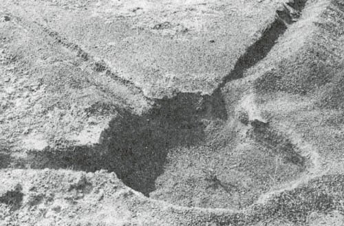


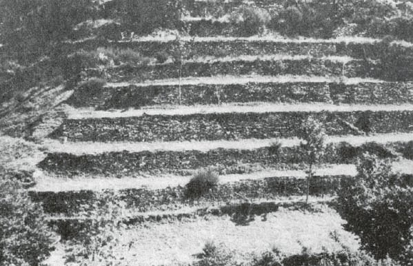


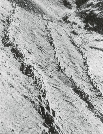


 ).
).


