 |
| ||||||||||||||||||||||||||||||||||||||||||||
|
| ||||||||||||||||||||||||||||||||||||||||||||
Institut f�r berufliche Entwicklung e.V.
Berlin
Original title:
Arbeitsmaterial f�r den
Lernenden
“Federverbindungen”
Author: Frank Wengh�fer
First edition © IBE
Institut f�r berufliche Entwicklung e.V.
Parkstra�e
23
13187 Berlin
Order No.: 90-35-3134/2
|
| ||||||||||||||||||||||||||||||||||||||||||||
Introduction
The present handbook is meant for practical vocational training in fields where - in additional to manual and mechanical metal working - mastery of assembly operations is required.
It describes the various kinds of joint that can be made with feather keys and profile shafts according to the function of the respective component groups.
The making and detaching of feather joints are explained by their major sequences of operation. In support, each section is followed by control questions the answering of which enables the trainee to check his knowledge.
|
| ||||||||||||||||||||||||||||||||||||||||||||
Hints on Labour Safety
In principle, the regulations on labour safety are applicable which have to be observed with the techniques of filing, scraping, drilling, reaming, milling and shaping. Special attention has to be paid to the following main points:
- Use only clean and sharp tools are which not defective.- Workpieces must be firmly and safely clamped - but so that they are not damaged.
- Keep the measuring and testing tools carefully and protect them against damages by shock and corrosion.
- Keep the workshop place in order, keep individually manufactured fitting pieces only together with their counterparts.
|
| ||||||||||||||||||||||||||||||||||||||||||||
1. Purpose of Feather Key Joints
Feather key joints detachable joints positively connecting parts, which have to do rotar motions, by fastening devices - feather keys.
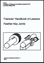
Figure 1 Feather key joint
1 key, 2 shaft, 3 hub
Feather key joints are made in order to
- connect parts of machines which have to carry out a true rotary movement;- to additionally secure the position of machine parts connected by clamping and taper connections, so that they are able to carry out a true rotary movement;
- to connect machine parts with shafts in such a way that, in addition to a rotating movement, they are also able to do an axial reciprocating movement.
Special advantages of the feather key joints
- The true running of the parts is guaranteed;
- The stability of the joint is guaranteed even with the transmission of higher rotary power.
Disadvantage
- The joint does not stand frequently changing discontinuous stress.
If shafts and hubs are shaped in a special way, the connection of rotating parts is guaranteed by this special shape itself. Additional feather keys are then no more required. Such shafts are called profile shafts; the hub is shaped corresponding to the profile of the shaft.
|
| ||||||||||||||||||||||||||||||||||||||||||||
2. Kinds of Feather Keys and Profile Shafts
Mostly, feather keys are made from drawn flat steel and have a tensile strength between 600 and 800 MPa. They may also be made by hand from sectional steel, if they are not available in the required dimensions.
Flat keys
These are elongated, rectangular bodies, straight or round-ended. For special functions within the joint they may be provided with bore holes to receive fillister-head screws. In addition, there may be a tapped hole in the centre of the key that enables that the key can be pressed out of the keyway with the help of a screw.

Figure 2 Flat keys
1 straight-ended, 2 round-ended, 3 with bore hole for locking screw, 4 with bore holes for locking screws and tapped hole for forcing screw
Woodruff keys
These are bodies that have the shape of a segment of a circle. They can transmit only low rotary powers, because the shaft keyway, which must be very deep, limits the strength of the shaft. They mainly secure the position of drive parts.

Figure 3 Woodruff key
Circular arc profile shafts
These shafts are also called K-shaped shafts or polygon shafts. They have a cross section in the form of a rounded equilateral triangle with long circular arcs as sides, and they are manufactured on profile turning machines or grinding machines.
They are able to transmit high rotary powers, because they create no notch effect. They are suitable for fitting connections of shaft and hub as well as for sliding connections, if the hub must be arranged in a movable way on the shaft.

Figure 4 Circular arc profile
shaft
Spline shafts
These are shafts in the periphery of which an even number of splineways are cut at regular intervals. The splineways are rectangular and may be of different depth corresponding to the stress they have to stand. These shafts are preferably used for highly stressed couplings and speed-changing mechanisms of changing rotational direction. The internal profile of the hub is made on shaping or broaching machines.

Figure 5 Spline shaft
Serrated shafts
These are shafts in the periphery of which trapeziform internal teeth (serration) are cut at regular intervals; the internal teeth have straight or rounded flanks. The shafts are used with high and discontinuous rotary powers, but they are not suitable, if parts on them shall be shifted under load. Often, the hub is slotted and clamped on the shaft by a screw.

Figure 6 Serrated shaft
Hints for manufacturing feather keys
- Feather keys are made by hand only, if industrially prefabricated keys are not available. They can be worked with files and scrapers.- Because the flanks of the feather keys are stressed, they must be carefully flattened by the file. To enable an accurate fitting in, they should be profiled with a slight allowance of 0.2 mm.
Sequence of operations
- Measuring of the shaft keyways and initial material;
- Testing of the clearance fit between shaft and hub;
- Filing the feather key true to size, slightly chamfering the edges;
- Drilling the holes for the holding screw as well as the tapped hole for the forcing screw;
- Putting in and fining of the feather key in the shaft keyway.
What are feather key
joints?
__________________________________________________________________________
__________________________________________________________________________
__________________________________________________________________________
What are the special advantages of feather key
joints?
__________________________________________________________________________
__________________________________________________________________________
__________________________________________________________________________
What is the disadvantage or feather key
joints?
__________________________________________________________________________
__________________________________________________________________________
__________________________________________________________________________
What kinds of feather keys are
distinguished?
__________________________________________________________________________
__________________________________________________________________________
__________________________________________________________________________
|
| ||||||||||||||||||||||||||||||||||||||||||||
3. Kinds of Feather Key Joints
Feather key joints are distinguished by the function of the feather key within the joint.
Fitting key joints
They serve for fixing a machine part on a shaft, if the respective part need not be moved on the shaft. The keys are placed into accurately fitting shaft keyways and only transmit the rotary power between shaft and hub.

Figure 7 Fitting key joint
1 fitting key, 2 shaft, 3 hub, 4 keyway of the fitting key in the shaft
Sliding key joints
They serve for fastening machine on parts on a shaft allowing the parts to slide on the shaft in an axial direction, e.g. transmissions. The keys are fixed by countersunk fillister-head screws, so that a displacement of the key in the keyway is prevented.

Figure 8 Sliding key joint
1 sliding key, 2 shaft, 3 hub, 4 keyway of the sliding key in the shaft
Profile shaft joints
- When connecting hubs with circular arc profile shafts or spline shafts the principles of feather key or sliding key joints apply.- When connecting hubs with serrated shafts, the principle of fitting key joints applies.
|
| ||||||||||||||||||||||||||||||||||||||||||||
4. Stress on the Feather Key Joints
Feather key joints are positive connections - the feather key sticks in a keyway that matches its form, without any preload.
As long as the machine parts are at rest, no forces are acting on the feather key, only when the rotary movement is started the rotary power is transmitted via the flanks of the feather key from one machine part to the other. The unit pressure at the flanks of the feather key acts on approximately half the height of the feather key. Opposite forces that are applied cause shear stresses at the level of the shaft circumference, which - with too high or discontinuously changing stress - may lead to the feather key shearing off.

Figure 9 Stress applied to the
feather key joint
1 shearing stress, 2 applied forces, 3 rotary power
Changing rotary directions have to be avoided, because this may cause a wearing out of the keyway, so that the feather key does no more stick.
If highly stressed joints for alternating rotary directions are to be manufactured through, profile shafts must be used.
What kinds of feather key joints are
distinguished?
__________________________________________________________________________
__________________________________________________________________________
__________________________________________________________________________
What kind of stress is a feather key in a joint exposed to
during the transmission of
power?
__________________________________________________________________________
__________________________________________________________________________
__________________________________________________________________________
|
| ||||||||||||||||||||||||||||||||||||||||||||
5. Tools, Devices and Auxiliary Means
Shank cutters and side milling cutters
Shank cutters are used for making round-ended keyways in shafts for fitting key and sliding key joints. Side milling cutters are used for the production of long, ending keyways in shafts for flat keys as well as circular keyways in shafts for Woodruff keys.
Figure 10 Manufacturing of
shaft keyways by
1 shank cutter, 2 side milling cutter
Broaches and keyway cutting tools
Broaches and keyway cutting tools are used depending on the respective techniques of “broaching” or “shaping” on the respective machines for the production of hub keyways.

Figure 11 Manufacturing of hub
keyway by
1 internal broach, 2 keyway cutting tool
Files and scrapers
Finishing files as well as triangular and flat scrapers are used for deburring the keyways and keys and for re-working and fitting in of the keys in the keyways.

Figure 12 Files and scrapers
Presses and screwing devices
Various kinds of presses and screwing devices are used, by which the keys can be forced into the keyway of the shaft evenly and without canting.
In a simple case, a parallel vice with light metal protective jaws is used.
Figure 13 Screwing device with
Vee support
Hammers and non-ferrous metal drift pins
Light metal hammers are used for loosening the machine parts as well as locksmith’s hammers and non-ferrous metal drift pins for drifting keys out of ending keyways.
Figure 14 Hammers and
non-ferrous metal drift pins
Pliers and screw drivers
Adjustable pliers are for loosening sticking feather keys out of the shaft keyways, pliers for shaft snap rings as well as screw drivers for fastening and loosening holding bolts and forcing screws in sliding feather keys.

Figure 15 Assembly tools
1 adjustable pliers, 2 pliers for shaft snap rings, 3 screw driver
Extractors
Extractors or pullers are used for pulling the hub from the shaft, if these machine parts stick together very firmly and must be loosened.

Figure 16 Puller (extractor)
What technique is used for making the keyways in the
shafts?
__________________________________________________________________________
__________________________________________________________________________
__________________________________________________________________________
What techniques are used for making the keyways in the
hubs?
__________________________________________________________________________
__________________________________________________________________________
__________________________________________________________________________
What techniques are used for reworking of feather
keys?
__________________________________________________________________________
__________________________________________________________________________
__________________________________________________________________________
|
| ||||||||||||||||||||||||||||||||||||||||||||
6. Technological Processes for Manufacturing Feather Key Joints and Profile Shaft Joints
There are only slight differences between the sequences of operations for manufacturing the different kinds of feather key joints.
6.1. Fitting Key Joints
Preparation of the keyway
For the manufacture of feather key joints it is necessary that keyways are cut into the parts to be connected for receiving the keys. This premachining is done by milling, broaching or shaping.
Figure 17 Individual parts
with premachined keyways
|
Do not scrape or file shaft keyways by hand - they will be inaccurate and the correct position of the fitting key will not be guaranteed. |
Checking of the individual parts
The external condition and dimensional accuracy of the hub and the shaft must be checked. In doing, so find out if
- the shaft has a clean surface (no defects);- the hub bore hole has no steps or marks;
- length, width, depth and alignment of shaft keyway and keyway in hub are true to size (according to working drawing by vernier caliper, depth gauge and others);
- the fit size of the shaft is exactly maintained (according to working drawing by external limit gauge);
- the fit size of the hub is exactly maintained (according to working drawing by plug limit gauge).

Figure 18 Checking of the
individual parts
1 length of the keyway of the shaft, 2 depth of the keyway of the shaft, 3 fit size of the shaft, 4 alignment of shaft keyway, 5 width of the keyway of the shaft, 6 width of the keyway of the hub, 7 depth of the keyway of the hub, 8 fit size of the hub
Deburring of the individual parts
Fitting key and keyways in shaft and hub are to be checked for buns. If burrs are found, they are removed by file or triangular scraper.
Fitting in of the fitting key into the keyway of the hub
The hub is clamped in a vice between protective jaws.
The fitting key is shoved through the keyway of the hub by slight pressure of the hand. If the fitting key gets stuck, the lateral surfaces of the keyway of the hub are carefully refiled - pay attention that the surfaces are worked evenly in order to guarantee that the fitting key is situated right in the middle.
Figure 19 Fitting in of the
key in the keyway of the hub
Fitting in of the fitting key in the keyway of the shaft
By a press or screwing device, the fitting key is forced into the keyway of the shaft evenly and without canting.
Figure 20 Fitting in of the
key in the keyway of the shaft
|
Do not force in the fitting key by a hammer - it will be canted and damaged at the top and side surfaces. |
The key must perfectly fit to the internal side surfaces of the keyway of the shaft, otherwise it may be torn out of the keyway when the rotary power is applied.
If absolute accuracy is required, the fitting key must be fitted in by scraping: By this technique, the side surfaces of the fitting key are worked in such a way that it is placed in the keyway in a slight press fit
Checking of the fit of the fitting key
The fit of the fitting key has to be checked. In doing so, make sure that
- the fitting key is parallel to the axis of the shaft;
- the height of the fitting key is invariable over the total length.
For testing this, profile gauges, go gauges or dial gauges can be used.
|
When a dial gauge is used, the shaft must be placed safely on Vee supports. For the dial gauge, a stand that can be locked in position is required. |

Figure 21 Checking of the fit
of the fitting key for central and parallel position
1 profile gauge ring, 2 dial gauge
If the fitting key does not fit properly, find out if there had already been shortcomings with the machining of the keyway. In this case, the shaft has to be replaced or the fitting key has to be reworked till the correct fit is achieved.
Assembly of the individual parts
The shaft journal with the key and the hub bore hole are slightly greased. With clearance fit between shaft and hub, the hub is put on the shaft straight and shoved over the fitting key by hand power.
With press fit (interference fit) between shaft and hub, the hub must be forced over the shaft in hot condition and with the help of a press.
The shaft may be previously cooled, if possible.
|
When heated, the hub expands slightly thus causing a widening of
the bore hole, too. |
When putting the parts together, make sure that the hub is not applied in a canted way and that the keyway of the shaft and the keyway of the hub are aligned.
Figure 22 Assembly of
the individual parts
Checking of the joint
After assembly, make sure that
- between the back of the fitting key and the keyway of the hub there is a clearance of approximately 0.2 mm;- the fitting key does not clatter;
- the hub is seated in its correct place on the shaft;
- true-running of the hub on the shaft is ensured.
Figure 23 Checking of the
joint
With clearance and transition fits between shaft and hub, the hub must be locked on the shaft to prevent an axial displacement of the hub.
For this purpose, shaft snap rings or retainer rings (circlips) are fixed on the right and left side of the hub. The therefore required radial grooves in the shaft must be free and placed exactly on the left of the hub.
Figure 24 Axial locking by
shaft snap ring
1 hub, 2 shaft, 3 grooves for shaft snap rings, 4 shaft snap ring
What are the criteria for checking the individual parts, if a
fitting key joint shall be
made?
__________________________________________________________________________
__________________________________________________________________________
__________________________________________________________________________
How tight must be the fit of the fitting key in the keyway of
the
shaft?
__________________________________________________________________________
__________________________________________________________________________
__________________________________________________________________________
How can a hub be placed on the shaft, if there is press fit
(interference fit) between the two
parts?
__________________________________________________________________________
__________________________________________________________________________
__________________________________________________________________________
What are the criteria for checking after a fitting key joint has
been
made?
__________________________________________________________________________
__________________________________________________________________________
__________________________________________________________________________
How can the axial displacement of the hub on the shaft
prevented?
__________________________________________________________________________
__________________________________________________________________________
__________________________________________________________________________
6.2. Sliding Key Joints
The sequence of operations is similar to that for manufacturing fitting key joints:
- Preparation of the keyway.
- Checking of the individual parts.
- Deburring of the individual parts.
- Fitting in the sliding key into the keyway of the hub.
- Fitting in of the sliding key in the keyway of the shaft.
- Checking of the fit of the sliding key.
- Assembly of the individual parts.
- Checking of the joints.
Differences in comparison with the fitting key joints are to be found with the fitting in of the key in the key-way of the shaft as well as with the assembly of the individual parts.
Fitting in of the sliding key in the keyway of the shaft
The sliding key is pressed into keyway of the shaft by hand - it must slip in easily. If this is not possible, the side surfaces of the key must be reworked.
According to the dimensions of the bore holes for the holding screws, the shaft is marked at the side. The sliding key is removed, so that the holes can be tapped for the holding screws.
Then, the sliding key is put into the cleaned keyway of the shaft and locked by matching holding screws.

Figure 25 Fitting in and
securing of the sliding key
Assembly of the individual parts
Between shaft and hub there must be an easily adjustable clearance fit. Otherwise, the hub must be reamed by a spiral-fluted reamer.
After this has been checked, shaft and hub are sligthly greased and assembled by hand - large parts with the help of hoisting machines.
What enables the firm fit of the sliding key in the keyway of
the
shaft?
__________________________________________________________________________
__________________________________________________________________________
__________________________________________________________________________
What kind of fit is required between shaft and hub with a
sliding key
joint?
__________________________________________________________________________
__________________________________________________________________________
__________________________________________________________________________
6.3. Profile Shaft Joint
The following steps have to be completed:
- Preparation of the keyways.
- Checking of the individual parts
- Deburring of the individual parts.
- Assembly of the individual parts.
- Checking of the joint.
Corresponding to the characteristic design of the various profile shafts, the individual steps are carried out as described for the fitting key and sliding key joints. Special attention has to be paid that
- the external profile of the shaft and the internal profile of the hub match accurately;
- the parts have no scratches or other defects;
- any burrs are removed from the external edges;
- no chips or other contamination are to be found in the keyways;
- the machine parts are assembled carefully and without canting.
|
| ||||||||||||||||||||||||||||||||||||||||||||
7. Detachment of Feather Key Joints
Parts of machines, which shall be dismantled and reassembled after maintenance or repair, have to be marked before dismantling. This will help to reassemble them correctly.
7.1. Detachment of Shaft and Hub
If there is a clearance fit between shaft and hub, the parts can be separated by hand power, if the external locking elements, such as shaft snap rings and retainer rings, had been removed before.
With transition and interference fits between shaft and hub, the parts must de drawn apart by a suitable puller.
With smaller units also presses may be used.
With very tight interference fits between shaft and hub, the hub must be thoroughly heated within a short time.
Short, systematic hammer blows must be done directly against the shaft journal, then the puller is applied, the screw is actuated and the hub is drawn off.
Figure 26 Detachment of shaft
and hub by the puller
7.2. Detachment of Feather Key from the Keyway of the Shaft
Feather keys without locking screws often stick in the keyway of the shaft very tightly, because they are held by the tight fit and the oil.
They must be gripped by suitable adjustable pliers and lifted in vertical direction. If the spring sticks in the keyway very tightly, careful hammer blows in connection with a non-ferrous metal drift pin will enable the loosening of the spring in the keyway. The hammer blows must be done in axial direction only. With ending keyways, the key may be pushed towards the end of the shaft. If the key is fastened by retaining screws, these must be unscrewed first. Then, the key can be taken out. Keys that have a tapped hole for a forcing screw are easy to remove out of the keyway:
A suitable screw with a long stud is screwed into the bore hole. The stud, while being turned, exercises pressure against the keyway of the shaft thus lifting the key upwards.
Figure 27 Detachment of
the key from the keyway of the shaft by forcing screw and screw driver
How is a fitting key joint detached, if there is an interference
fit between shaft and
hub?
__________________________________________________________________________
__________________________________________________________________________
__________________________________________________________________________