 |
| ||||||||||||||||||||||||||||
|
| ||||||||||||||||||||||||||||
Institut f�r berufliche Entwicklung e.V.
Berlin
Original title:
Arbeitsmaterial f�r den Lernenden
“Einrichten und
Bedienen von Waagerecht- oder Senkrechtfr�smaschinen”
Author: Dieter Frank
First edition © IBE
Institut f�r berufliche Entwicklung e.V.
Parkstra�e
23
13187 Berlin
Order No.: 90-35-3301/2
|
| ||||||||||||||||||||||||||||
1. Purpose and importance of milling
The milling technique is used to machine and produce workpieces made of free-cutting material.
Milling is a metal cutting operation with the cutting done by a single-edged or multi-edged tool, the milling cutter.
The milling cutter performs a rotary movement (primary motion) and the workpiece a linear movement (secondary motion).
The milling technique is used to produce, mainly on prismatic components, flat, curved, parallel, stepped, square and inclined faces as well as slots, grooves, threads and tooth systems.
There are two basic milling methods: plain (or cylindrical) milling and face (or end) milling. Either method may be up-cut (or conventional) milling or down-cut (or climb-cut) milling. Plain milling and face milling differ with respect to the milling cutters or cutting edges (teeth) used in the cutters, respectively, and to the direction of feed.
Plain milling (cylindrical milling)
The peripheral teeth are cutting.
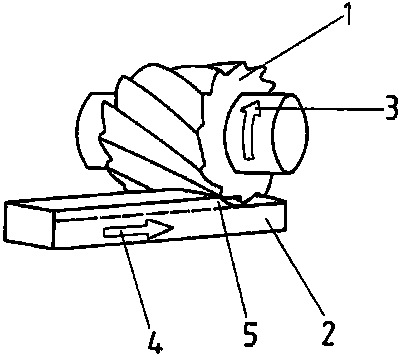
Figure 1. Working motions of plain
milling
1 plain milling cutter, 2 workpiece, 3 direction of rotation, 4 feed direction, 5 cross-sectional area of cut
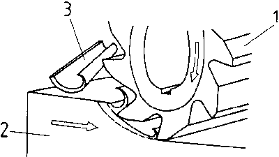
Figure 2. Plain milling cutter in
action
1 plain milling cutter, 2 workpiece, 3 comma-shaped chip
Face milling (end milling)
The radial and peripheral teeth are cutting.
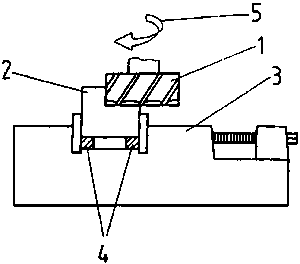
Figure 3. Face milling cutter (face
milling of a stepped face)
1 face milling cutter, 2 workpiece, 3 machine vice, 4 parallel blocks, 5 direction of rotation of cutter

Figure 4. Face mill during face
milling
Up-cut milling (conventional milling)
The primary motion of the milling cutter and the secondary motion of the workpiece are in opposite directions.
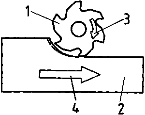
Figure 5. Up-cut milling
1 milling cutter, 2 workpiece, 3 direction of rotation of cutter (primary motion), 4 feed direction of workpiece (secondary motion)
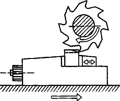
Figure 6. U-cut milling (workpiece
clamped in machine vice)
Down-cut milling (climb-cut milling)
The primary and secondary motions (cutter and workpiece motions) are in the same direction.
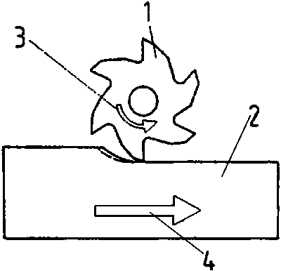
Figure 7. Down-cut milling
1 milling cutter, 2 workpiece, 3 direction of rotation of cutter (primary motion), 4 feed direction of workpiece (secondary motion)
Down-cut milling calls for the following technical prerequisites:
- For elimination of the backlash between the machine table screw and screw nut, a climb-milling attachment (backlash eliminator) is necessary.- The increased cutting values of down-cut milling (1.5 times the cutting values of up-cut milling are possible) necessitate a low-vibration bearing of the cutter arbor (two counter bearings are recommended for plain milling on the horizontal milling machine) and the workpiece must be additionally secured in the direction of feed.
- Milling cutters with small wedge angle and relatively big rake angle reduce the cutting impacts and extend the cutter life. The cutting teeth are in action on the maximum thickness of chips.
Down-cut milling is possible only on milling machines with climb-milling attachment.
For down-cut milling the workpiece and workpiece clamping device must be fixed so that the workpiece cannot be pulled to the cutter jerkily. (Danger of accidents/tool breakage).
What is the difference between plain milling and face
milling?
________________________________________________
________________________________________________
________________________________________________
________________________________________________
What are the technical prerequisites absolutely necessary for
down-cut
milling?
________________________________________________
________________________________________________
________________________________________________
________________________________________________
What is the difference between up-cut and down-cut
milling?
________________________________________________
________________________________________________
________________________________________________
________________________________________________
|
| ||||||||||||||||||||||||||||
2. Types and design of milling machines
The types of milling machines or their names, respectively, are attributable to their application or construction.
Basic types:
- Knee-type milling machines (horizontal or vertical)
- Ram-type (or saddle-type) milling machines
- Piano-milling machines
- Keyway and slot milling machines
- Form copying and engraving millers
- Thread milling machines
- Gear milling machines
- Special milling machines.
Knee-type milling machines are the most popular machines among the above-mentioned types since, in conjunction with additional attachments, they have a wide field of application. For example, the following additional attachments are available: vertical milling head, universal milling head, rotary indexing table, universal indexing head, slotting attachment.
Knee-type milling machines consist of three main units:
- Frame: base plate, column, overarm, counter bearing, knee, saddle and machine table.- Drive: milling/spindle drive, feed drive and other drives for special attachments between milling cutter and workpiece.
- Control: elements and devices to control the relative movements between the cutter and workpiece.

Figure 8. Horizontal milling machine
1 base plate, (base) 2 column, 3 knee, 4 saddle, 5 machine table (table), 6 overarm, 7 counter bearing, 8 screw nut for knee movement, 9 coolant return line, 10 cutter arbor (long arbor), 11 main control console (control panel), 12 auxiliary control console, 13 main switch, 14 selector switch, 15 main hand adjustment, 16 auxiliary hand adjustment, 17 guideways, 18 guideway covers, 19 speed selector lever, 20 speed dial scale, 21 feed selector lever, 22 feed dial scale, 23 directions movements (X, Y, Z axes)

Figure 9. Vertical milling machine
1 top of column (angled towards the front), 2 milling spindle head (swivel type)
Up to the A-B-C plane the frame of the vertical milling machine is similar to that of the horizontal milling machine.
Above that level, the column (1) is angular towards the front and provided with a mount for the swivel-type milling spindle head (2). Thus the milling spindle head can be swivelled to the left and right by 45 degrees each.
|
| ||||||||||||||||||||||||||||
3. Preparation for setting-up and operation of horizontal or vertical milling machines
Prior to operating the milling machines, all tools and accessories are to be placed at disposal properly and conveniently and within easy reach observing the following rules:
- Working tools must not lay one above another.- Measuring and testing tools are to be stored on suitable supports (soft supports: rubber and felt supports).
· Hammer and file handles must be firmly fixed and not be damaged.· Spanners (open-ended, box and ring spanners), hand and vice cranks must be free from burrs and have the proper size for the purpose of use (bent up openings at spanners and too big spanners/cranks must not be used).
· Clamping tools (machine vices, fixtures, clamping elements) must be suitable for the purpose of locating and fixing.
· Clamping tools for milling cutters (cutter arbors, chucks, collets) must be complete and not be damaged (arbor collars, feather keys, bushings, cap nuts, etc.).
Figure 10. Clamping tools for milling cutters

(1) stub arbor (short arbor) 1 cross screw, 2 driver, 3 feather key(2) cutter arbor (long arbor) 1 arbor, 2 arbor collars, 3 bush, 4 arbor nut, 5 machine taper (steep taper)
· Tools are to be stored in clean condition.· All auxiliaries necessary are to be selected according to the work to be done and to be kept ready on proper supports.
Milling of workpieces necessitates firm fixing of the workpieces and cutters. Fixing of workpieces and cutting tools is called “clamping”.
Clamping of workpieces for milling
Clamping of workpieces serves two purposes:
- locating the workpiece, and
- fixing the workpiece.
Locating the workpiece means defining the position and direction of the workpiece depending on the cutter and on the dimensions and datum faces shown in the working drawings.

Figure 11. Machine vice located by
sliding blocks
1 machine vice, 2 milling table (machine table), 3 sliding blocks, 4 clamping screws
Fixing of the workpiece serves the purpose of holding (retaining) the workpiece during milling in the position where it has been located.
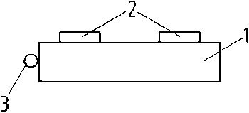
Figure 12. Workpiece located by
sliding blocks and stop
1 workpiece, 2 sliding blocks, 3 stop
There are several possibilities for clamping of workpieces which depend on various factors, such as:
- the geometrical form (e.g. cylindrical or prismatic) and the size of the workpiece and its rigidity (thin-walled, hollow casting or square steel part),- the position of the face of the workpiece to be machined,
- the number and frequency of the workpieces to be machined,
- the selection of clamping tools available and the type of the milling machine used (horizontal or vertical milling machine).
Mostly used clamping facilities include:
- Machine vice (available in various versions).
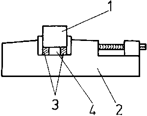
Figure 13. Clamping in machine vice
1 workpiece, 2 machine vice, 3 parallel blocks, 4 machined surface
- A variety of holding clamps, clamping screws and set-up blocks.

Figure 14. Holding clamps
(1) flat clamp, (2) channel-type, (3) fork-type, (4) offset at one end, (5) offset at two ends
- Sliding blocks, for locating machine vices or directly locating workpieces.
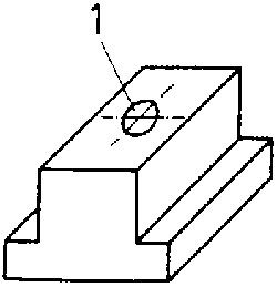
Figure 15. Sliding blocks
1 sliding block with hole for fixing screw
- Angle plates of solid, rotary and swivelling types.

Figure 16. Angle plates
(1) angle plate (90°), (2) angle plate (clamping table), rotary and swivelling
- Chuck jaws with or without rotary base plate.
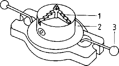
Figure 17. Jaw chuck
1 three-jaw chuck, 2 base plate with scale, 3 control lever
- Workholding fixtures for single or multi-component set-ups.
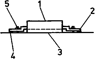
Figure 18. Workholding fixture in
direct table clamping
1 workpiece face to be machined, 2 holding clamp, 3 first face machined, 4 support, 5 clamping screw with nut and washer
- Indexing attachments, direct-indexing attachments, universal indexing attachments, rotary indexing tables.
- Clamping auxiliaries, such as stop bars, Vee-jaws, pre-clamping angle plates and clamping mounts for rotary-table indexing.
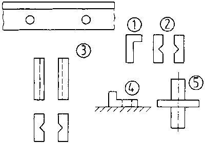
Figure 19. Clamping accessories
(1) stop bar with holes for fixing screws, (2) Vee-jaws (horizontal vee), (3) Vee-jaws (vertical vee), (4) pro-clamping angle plates, (5) clamping mount for rotary indexing table and locating hole in workpiece
Workpiece clamping tools and auxiliaries must serve the following purposes:
- Firm holding (fixing) of the workpiece to secure them against displacement by forces applied during milling.- Exact and definite location of the workpiece.
- Ensuring sufficient stability and rigidity to permit full utilization of the machine and cutter.
- Quick and easy change of workpieces without any danger.
When clamping the workpieces it is to be made sure that the workpieces, clamping auxiliaries (e.g. jaws of the machine vice) and clamping supports are clean and free from burrs.
Any impurities and burrs will result in deviations from the location and, consequently, from the dimensions of the workpiece and in damage to the workpiece surface.
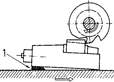
Figure 20. Impurities in clamping
1 chip under machine vice
When clamping thin-walled or instable components it is to be made sure that the clamping force will not deform the workpiece so that it becomes unusable.
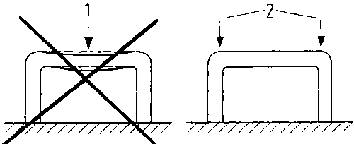
Figure 21. Thin-walled, instable
workpiece
1 wrong clamping area - workpiece becomes deformed, 2 favourable clamping areas
Why is it necessary to use serviceable tools and auxiliaries
only?
________________________________________________
________________________________________________
________________________________________________
What are the criteria for the selection of workpiece clamping
tools?
________________________________________________
________________________________________________
________________________________________________
________________________________________________
Clamping of milling cutters
Clamping tools for milling cutters differ with respect to the purpose of use and geometrical form:
- Cutter arbors, long or short (stub arbors)
- Cutter chuck,
for straight-shank cutters
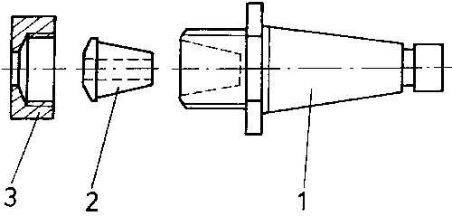
Figure 22. Clamping tools for milling
cutters
1 cutter chuck, 2 collet, 3 cap nut

Figure 23. Straight-shank cutter
(shank-type milling cutter)
- Cutter adaptor, for taper-shank cutters

Figure 24. Taper-shank cutter
(shank-type milling cutter)
- Direct mounting of cutters on the milling spindle
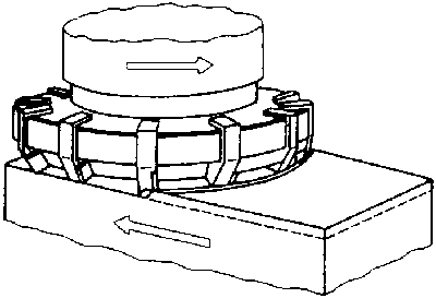
Figure 25. Cutter directly clamped on
milling spindle (face milling cutter)
Cleanliness must be ensured when clamping the milling cutters in the clamping tools. Impurities (e.g. chips, dust, sand, etc.) on the contact faces or between the arbor collars will adversely affect the cutting process by radial or axial runout.
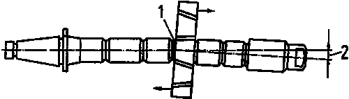
Figure 26. Impurities between cutter
and arbor collar
1 impurities, 2 radial runout
- When using long arbors on the horizontal milling machine, the counter bearing is to be placed as close to the cutter as possible to prevent or reduce vibrations generated during milling

Figure 27. Counter bearing directly
at the cutter
1 overarm, 2 cutter, 3 counter bearing, 4 cutter arbor
Vibrations during milling result in deterioration of the surface finish of the workpiece, reduction of the feed rate and early wear of the cutter. The use of a second counter bearing (at the front and rear of the cutter) offers an additional possibility of further reducing vibrations generated, particularly in cases where thick chips are to be removed.

Figure 28. Use of two counter bearings
1 overarm, 2 cutter, 3 counter bearings, 4 cutter arbor
What can be done to reduce vibrations during milling with a long
arbor?
________________________________________________
________________________________________________
________________________________________________
________________________________________________
________________________________________________
________________________________________________
|
| ||||||||||||||||||||||||||||
4. Setting-up and operation of horizontal or vertical milling machines
Setting-up of milling machines means the preparation of the milling machines for milling. The selection of the clamping tools for the cutters, of the clamping tools for the workpieces and setting of the cutting values, speed rate, feed rate and depth of cut, are necessary prior to milling.
Proper setting-up and operation of the milling machine are prerequisites for carrying out the milling operation successfully. Errors, such as the selection of an unfavourable way of clamping or sequence of the individual steps, will result in defects in quality of the workpieces machines. The amount of work will be considerably increased.
Setting-up and operation of horizontal or vertical milling machines involves the following steps:
1. Planning the work cycle.2. Making available the cutting tools, measuring and testing tools as well as clamping tools.
3. Checking the cutting tools, measuring and testing tools and clamping tools for serviceability.
4. Checking the milling machine for proper working order:
- existence and state of controls (switches, push-buttons, crank handles),
- oil level (bubble glasses and sight glasses) as well as identified lubrication points,
- existence of safety facilities on the milling machine (covers, hoods, cutter guards).
5. Making available sufficient and adequate coolant.6. Checking for existence and serviceability of end stops on the milling table, knee and saddle.
Any defects found with the milling machine are to be reported immediately to the serviceman in charge to arrange for immediate repair.
If any additional or special attachments are to be used, such as vertical milling heads, universal milling heads, slotting attachments or power driven rotary indexing tables, they are also to be checked for serviceability and safety in operation prior to putting them into operation.
Defective additional attachments are to be replaced. The defective attachment is to be reported for repair.
- The cutting values (cutter speed and feed rates, number of cuts and the relevant depth of cut) are either to be read from the attached documents or to be calculated. They can also be read from the nomogram of the milling machine.
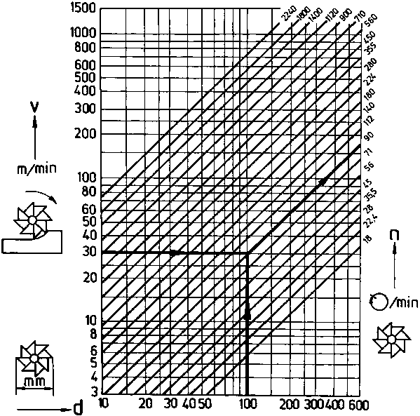
Nomogram
Example
The necessary rotational speed is to be determined for a cutter of 100 mm diameter (d) at 30 m/min cutting speed.
v = 30 m/min (value from table of cutting speeds for milling)
d = 100 mm
Reading for rotational speed (n) = 90 r.p.m.
The rotational speed read from the nomogram is to be set at the milling machine (see Fig. 8 in section 2, 19 - speed selector lever).
· The values determined are to be set by means of the relevant control elements of the milling machine (speed selection lever, feed selection lever and hand adjustment by means of the crank handle).· For setting the machine table with the clamped workpiece into working position at the cutter, coarse adjustment of the knee, saddle and machine table is made by rapid traverse and fine adjustment by hand.
· The coolant unit is to be positioned and set so that the coolant jet is directed directly on the cutting area. The coolant return line to the coolant tank in the base of the machine must be free from impurities.
- Functions of the coolant:
· Reducing the heat generated by friction between the cutter and workpiece (cooling and lubricating effect), and flushing away the chips from the immediate cutting area.If necessary, a splash guard and chip guard are to be fitted.
- The cutting value (depth of cut) is set after the “first scratch”. When the cutter is running, the milling table is moved by hand adjustment (crank handle) into the position where the cutting edges of the cutter take the first cut (first scratch).
- After the first milling pass (first cut) it is necessary to check the size and surface finish achieved (comparison with the data on the working drawing).
- After further setting of the depth of cut (until the final size is reached) and finish-milling and subsequent checking of
· the specified dimensions (tolerances),
· the accuracy of shape and position (flatness, parallelism, squareness)
· surface finish (roughness),
machining of the first workpiece is completed.
- For workpiece change (unclamping and clamping) the cutter must be stopped to prevent accidents (hand injuries).
- Metal chips must not be removed by fingers or cleaning rags (danger of injury by sharp-edged or pointed chips). A chip brush or hand broom is to be used.
NoteWhen chips are removed by means of compressed air, safety goggles are to be used to avoid injuries to the eyes.
For proper fulfillment of the work order it is necessary to observe and follow the specified steps (technological sequence) for setting-up and operating horizontal or vertical milling machines, including maintenance and servicing.
How are the cutting values for milling be
determined?
________________________________________________
________________________________________________
________________________________________________
________________________________________________
________________________________________________
________________________________________________
________________________________________________
What steps are required in setting-up and operating a milling machine?
1. ________________________________________________
2.
________________________________________________
3.
________________________________________________
4.
________________________________________________
5.
________________________________________________
6.
________________________________________________
What are the functions of the coolant in
milling?
________________________________________________
________________________________________________
________________________________________________
________________________________________________
________________________________________________
|
| ||||||||||||||||||||||||||||
5. Maintenance and servicing of milling machines
Like any other machine, milling machines are subject to wear and tear. The physical wear is a result of the use of the machines and of the abrasion caused by friction during use. Such wear can be reduced by regular maintenance and servicing of the milling machine by the operator:
The degree of wear depends on:
- maintenance and servicing of the milling machine,- properties of coolants and lubricants,
- environmental conditions (dust, temperature variations, etc.)
-operating conditions (single or multi-shift operation, volume of metal removed, proper operation).
Servicing cycle of milling machines:
|
Kind of servicing work |
Interval |
|
1. Cleaning of guideways |
daily |
|
2. Inspection of oil level (sight glasses) |
daily |
|
3. Lubrication as per lubrication chart |
as per instructions on lubrication chart |
|
4. Oil renewal |
semi-annually/annually |
|
5. Inspection and, if necessary, refilling of coolant tank |
weekly |
|
6. Thorough cleaning of the machine |
weekly |
|
7. Inspection of slackness of bearings |
annually |
|
8. Inspection of electrics (contactors, limit switches, cable connections) |
every 3 months |
|
9. Inspection of lubrication pump |
semi-annually |
|
10. Coolant renewal |
semi-annually |
For lubrication of a machine the following basic rule applies:
The specified lubricant is to be applied to the relevant lubricating point in the specified quantity and at the specified time!
It is absolutely necessary to observe the safety regulations for setting-up and operation as well as for maintenance and servicing in order to avoid accidents and interruptions of the production. Any defects found at the lubricating points of the milling machine are to be reported to the serviceman in charge. Repairs, particularly on the electrics, control elements and lubricating points, must be done by authorized specialists only.
For handling and storing lubricants, coolants, etc. the respective fire protection regulations (such as “no smoking” within 5 m; flash points of oil and grease) are to be strictly adhered to in order to prevent fire.
For setting-up, maintenance, servicing and repair work on the milling machine the main switch must always be in “OFF” position - danger of accidents!
What can be done to reduce the physical wear of the milling
machine?
________________________________________________
________________________________________________
________________________________________________
________________________________________________
________________________________________________
What is to be observed for handling (storing and using) oil and
lubricants?
________________________________________________
________________________________________________
What is the basic rule to be observed for setting-up,
maintenance and servicing work in the interest of labour
safety?
________________________________________________
________________________________________________
________________________________________________
________________________________________________
________________________________________________