 |
| ||||||||||||||||||||||||||||||||||||||||
|
| ||||||||||||||||||||||||||||||||||||||||
Institut f�r berufliche Entwicklung e.V.
Berlin
Original title:
Arbeitsmaterial f�r den Lernenden
"Nieten"
Author: Frank Wengh�fer
First edition © IBE
Institut f�r berufliche Entwicklung e.V.
Parkstra�e
23
13187 Berlin
Order No.: 90-35-3111/2
|
| ||||||||||||||||||||||||||||||||||||||||
1. Purpose of riveting
Riveting is the permanent connection of two or more workpieces the rivet being put as a joint in a predrilled bore hole and formed on one or both ends.

Figure 1 - Riveting
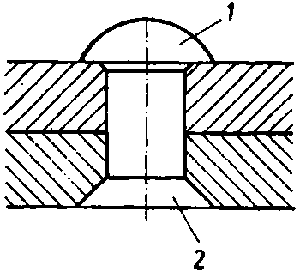
Figure 2 - Riveted connection
1 - Closing head (button head)
2 - Set head (countersunk-head)
The riveted parts can be connected in a movable, fixed, close or fixed and close manner. Shall the connection be undone, the rivet must be removed by destroying one of the two rivet heads.
Note:
When considering the kind of connection, check up if the material can be glued or welded - these techniques replace the method of riveting and are more economical as to time and material.
What characteristics can riveted joints
have?
________________________________________________________________________________________________________________________________________________________________
Why is riveting a permanent
connection?
________________________________________________________________________________
|
| ||||||||||||||||||||||||||||||||||||||||
2. Kinds of rivets
Rivets consist of tough steel (340 MPa), copper, brass and aluminium.
- Button head rivets:
They are used in components, where the projecting head does not disturb and are especially suitable for fixed and close joints, because a strong clamping effect is achieved by them.

Figure 3 - Button head rivet
- Countersunk-head rivet:
This is used in components or parts the surfaces of which must not become uneven by projecting rivet heads; it is not suitable for highly stressed connections.

Figure 4 - Countersunk-head rivet
- Oval head countersunk rivet:
They are used for such parts where the surface is rough and uneven and where no special demands are made on the quality of the surface or - on the contrary - an uneven surface shall be achieved (gangways, steel stairs - nonskid property).
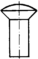
Figure 5 - Oval head countersunk
rivet
- Boiler construction rivet:
A button head rivet with conical shank, which can be easily put into not quite accurately aligned bore holes. This rivet is used in the construction of pressure vessels and boilers. By caulking the plate edges and rivet heads, close and fixed connections are achieved.

Figure 6 - Boiler construction rivet
- Explosive rivets:
These are used, if the components are accessible only from one side (light metal construction, aircraft manufacture). The explosive charge is electrically ignited thus widening the rivet shank.

Figure 7 - Explosive rivet
- Belt rivet:
The belt rivet is used for connecting soft materials such as leather, rubber, felt.
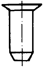
Figure 8 - Belt rivet
- Hollow civet or tubular rivet:
This kind of rivet is used to connect delicate materials - the hammering of the rivet head requires only little force.

Figure 9 - Hollow rivet
- Pin:
Components used in precision mechanics are sometimes equipped with a pin the projecting end of which can be worked like the shank of a rivet.

Figure 10 - Pin
What materials are rivets made
of?
________________________________________________________________________________
What qualities must these materials
have?
________________________________________________________________________________
When do you use button-head
rivets?
________________________________________________________________________________________________________________________________________________________________
When do you use countersunk head
rivets?
________________________________________________________________________________________________________________________________________________________________
|
| ||||||||||||||||||||||||||||||||||||||||
3. Kinds of riveted joints
Movable rivetings are always made in the form of individual rivetings; the parts can be moved against one another after being riveted.
Fixed rivetings are mostly made in the form of riveted seams at plates.
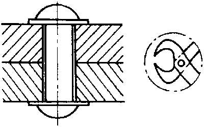
Figure 11 - Movable riveting
(example: tongs)
We distinguish between:
- Kind of joint - butt joints, lap riveted joints

Figure 12 - Single-row lap riveted
joint
- Number of rows - single-row, multirow

Figure 13 - Double-row parallel lap
riveted joint
- Arrangement of rivets - parallel, zigzag

Figure 14 - Double-row parallel butt
riveted joint
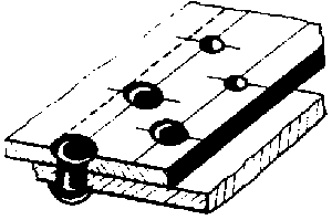
Figure 15 - Double-row zigzag butt
riveted
joint
|
| ||||||||||||||||||||||||||||||||||||||||
4. Tools and auxiliary means for riveting
- Riveting hammer:
These are locksmith's hammers of a weight between 50 g and 200 g. Hand hammers of a weight between 200 g and 400 g are also used.
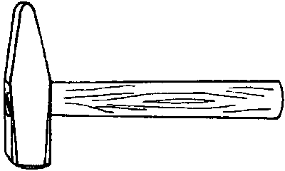
Figure 16 - Riveting hammer
Rivet setter:
It serves for setting the set head to the workpiece and for pressing on the plates to be riveted. The head bore side is hardened.

Figure 17 - Rivet setter
- Rivet header:
It serves for finish-forming the closing head of button head rivets after it had been preshaped by the hammer. The head recess is hardened and polished.

Figure 18 - Rivet header
Rivet support (counter holder):
This receives the set head of a button head rivet and is equipped with a head recess. There are fixed rivet supports for clamping in a vice as well as adjustable ones.The latter are placed under big workpieces and adjusted with the help of a screw.
For countersunk-head riveting, a surface plate or anvil can be used as rivet support.

Figure 19 - Fixed riveting support

Figure 20 - Adjustable riveting
support
- Clamping tools:
Various clamps or clamp dogs may be used for clamping the plates; in clamping jaws for round material, rivet bolts can be preformed.

Figure 21 - Clamping by hand vice
For hot-riveting, the following is required additionally:
- smith's fire (for heating up the rivets)
- rivet clamp (for holding the hot rivets)
- rivet tongs (for taking the rivets out of the fire)
For mechanized riveting, the following equipment is used:
- pneumatic riveter
- hydraulic riveter
Which tools and auxiliary equipment are used for cold-riveting
by
hand?
________________________________________________________________________________________________________________________________________________________________
What is the task of the rivet
setter?
________________________________________________________________________________________________________________________________________________________________
|
| ||||||||||||||||||||||||||||||||||||||||
5. Calculations for the selection of rivets
If on the working drawing no details on the rivet are indicated, the following has to be taken into consideration:
The diameter of the rivet shank shall be at least one quarter of the thickness of all plates to be riveted - formula:

D = diameter of the rivet shank
s = thickness of all plates to be riveted (clamping length)

Figure 22 - Riveted joint:
1 - Diameter of the rivet shank
2 - Length of the rivet shank
3 - Allowance
4 - Clamping length
The length of the rivet shank has to be calculated on the basis of the thickness of all plates to be riveted:
The rivet shank must be longer than the thickness of all plates to be riveted by the measure of the "allowance" - formula:
|
L = S + z |
L = length of the rivet shank
S = thickness of all plates to be riveted
Z = allowance
The allowance depends on the kind of rivet and on the field of application:
- Button closing heads in steel construction;
For rivets of diameters of the rivet shank up to 20 mm -
|
Z = 1.5 x D |
For rivets of diameters of the rivet shank of more than 20 mm -
|
Z = 1.6 x D |
- Button closing heads in boiler construction:
For rivets of rivet shank diameters up to 20 mm -
|
Z = 1.7 x D |
For rivets of rivet shank diameters of more than 20 mm -
|
Z = 1.8 x D |
- Countersunk closing heads in general:
|
Z = 0.5 x D |
Rivets which are too long must be cut - the right length of the rivet shank is the precondition of the quality of the closing head.
Calculating example:
A button head rivet shall be calculated in order to connect two plates of 4 mm in thickness in steel construction:
1. Diameter of the rivet shank:
|
|
D = 2 mm |
| |
selected: 3 mm |

2. Length of the rivet shank:
|
L = S + Z | |
|
Z = 1.5 x D = 1.5 x 3 mm |
Z = 4.5 mm |
|
L = 8 mm + 4.5 mm |
L = 12.5 mm |
| |
selected: 12 mm |
Result: A rivet with the designation button head rivet 3 x 12 can be used for the intended connection.
Exercise:
A countersunk riveting of three 5 mm thick plates shall be made
What rivet can be used for this
purpose?
________________________________________________________________________________________________________________________________________________________________________________________________________________________________________________________________________________________________________________________________
|
| ||||||||||||||||||||||||||||||||||||||||
6. Technological process of riveting
On principle, the following sequence of operations is necessary for a riveted connection:
6.1. Clamping/drilling:
All plates to be riveted must be clamped with one another as tightly as possible and be drilled together.
With separately drilled parts, attention has to be paid that misaligned holes are reamed by a structural reamer.

Figure 23 - Reaming of misaligned bore
holes
Rivet holes have to be drilled a little larger the diameter of the rivet shank:
For rivets thicker than indicated in the table, the bore holes are made by 1 mm larger than the diameter of the rivet shank.
|
Recommended values | |
|
D |
DB |
|
1 |
1.1 |
|
2 |
2.2 |
|
3 |
3.2 |
|
4 |
4.3 |
|
5 |
5.3 |
|
6 |
6.4 |
|
8 |
8.4 |
D = diameter of the rivet shank
DB = diameter of the bore hole
6.2. Deburring/countersinking;
Rivet holes are always debarred with the help of a countersinking cutter; for countersunk-head rivets, countersinking must be made by the 75° countersinking cutter. For this, the recommended values are to be found in the marginal table:

Figure 24 - Deburring/countersinking
|
Recommended values | |
|
D |
DS |
|
1 |
1.8 |
|
2 |
3.5 |
|
3 |
5.2 |
|
4 |
7 |
|
5 |
8.8 |
|
6 |
10.3 |
|
8 |
14 |
D = diameter of the rivet shank
DS = countersinking diameter
6.3. Inserting/setting
The rivet is inserted into the bore hole, the workpieces are placed on the riveting support in such a way that the set head is underneath. By hammer blows on the rivet setter, the plates are pressed together and the set head draws itself to the workpiece.

Figure 25 - Inserting/setting
6.4. Upsetting
By a couple of hammer blows accurately in the direction of the longitudinal axis, the rivet is upset - until it fills up the bore hole completely.

Figure 26 - Upsetting
6.5. Preforming/heading
By even and steady blows around the rivet head, the rivet head is preformed, if a button head riveting shall be made.

Figure 27 - Preforming
With countersunk-head rivetings, the rivet head can be driven into the countersinking immediately.

Figure 28 - Heading
6.6. Finish-forming of the button closing head
If the closing head has been preformed sufficiently, the head is finish-formed by the rivet header.

Figure 29 - Finish-forming
Note:
- Riveting by hand can be carried out in cold condition of the steel rivet up to approximately 8 mm diameter - thicker rivets must be worked in red-hot condition.- Non-ferrous metal rivets are worked in cold condition after having them annealed before.
With every cold working of steel or non-ferrous metal, the material becomes hard and brittle, especially if it is formed by many hammer blows. In order to keep the material as tough and elastic as possible, the rivet should be shaped by a few, well-aimed blows.
Peculiarities of the technological process
- If no prefabricated button head rivets or countersunk-head rivets are at disposal, steel or non-ferrous metal wires may also be used as rivet bolts.
In this case, the rivet bolt has to be clamped in clamping jaws for round material with a set head to be preformed.
If no clamping jaws for round material are at hand. the rivet bolt must be preheaded in the rivet hole, the set head is formed, then the workpiece is turned and the closing head is shaped.

Figure 30 - Sequence of operations
for a double-strap countersunk-head riveting with rivet bolt
- If hollow rivets shall be used, an allowance has to be calculated as it is done with countersunk-head rivets; the rivet -after having been inserted - is to be expanded by a centre punch and to be upset by two short blows.

Figure 31 - Hollow rivet expanded by
a centre punch
What individual steps are required for making a button head
riveting?
________________________________________________________________________________________________________________________________________________________________
What is to be done, if individually drilled parts - when being
put together - show misaligned
holes?
________________________________________________________________________________________________________________________________________________________________
What hole must be drilled for a 4 mm thick
rivet?
________________________________________________________________________________
What countersink do you use to prepare countersunk-head riveted
joints?
________________________________________________________________________________
How must the countersinking diameter be for a 4 mm
countersunk-head
rivet?
________________________________________________________________________________
|
| ||||||||||||||||||||||||||||||||||||||||
7. Loosening of a riveted connection
A riveted connection can be undone only by destroying the rivet.
For this purpose, one rivet head has to be chiselled off by a flat chisel, and the rivet has to be driven out of the hole with the help of a drift pin.

Figure 32 - Chiselling-off of rivet
heads
Beware of splitting off rivet heads - put up a safety lattices or safety guards.
Rivets can be destroyed also by drilling or grinding-off of the rivet heads.
|
| ||||||||||||||||||||||||||||||||||||||||
8. Riveting faults
- If the rivet shank is too long. the superfluous material forms a wreath at the head of the closing head.

Figure 33 - Riveting faults
- If the rivet shank is too short, the closing head is not sufficiently formed,
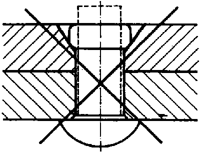
Figure 34 - Riveting faults
- If the plates are not enough tightened by the rivet setter, the shank is squeezed between the plates, a wreath appears and the closing head is not correctly formed.
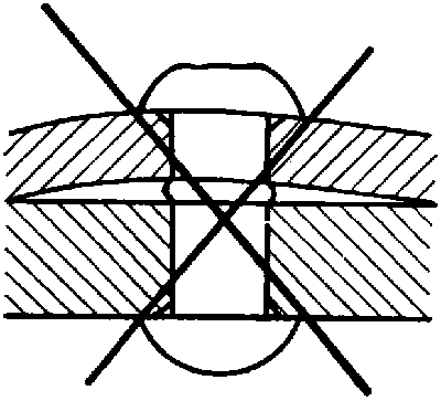
Figure 35 - Riveting faults
- If the hammer blows on the rivet setter are too strong, the upper plate is squeezed too much and bows.
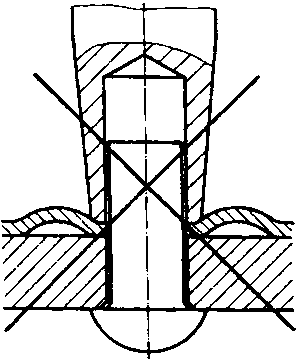
Figure 36 - Riveting faults
- If the bore holes are heavily misaligned, the rivet shank will be notched, so that the rivet cannot stand high shearing loads.
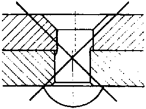
Figure 37 - Riveting faults
- If the rivet hole is too large, the rivet shank bends, the closing head is not formed.
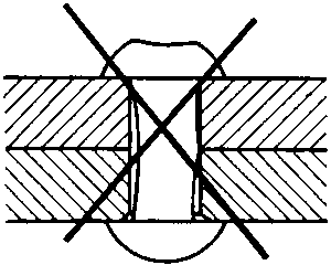
Figure 38 - Riveting faults
Note:
Use the corresponding rivet setter and rivet header for the rivet you have chosen,
Why shall only a few, well-aimed blows be made when riveting the
closing
head?
________________________________________________________________________________________________________________________________________________________________
How can riveted joints be
undone?
________________________________________________________________________________________________________________________________________________________________
What kinds of riveting faults could have been made if it is to
be seen that the closing head is not formed
correctly?
________________________________________________________________________________________________________________________________________________________________________________________________________________________________________________